


4
ASSEMBLY
WARNING: If received assembled,
review allassembly steps toensure your unit
is properly assembled and all fasteners are
secure.
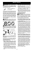
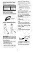
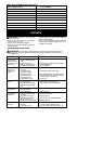
TUBE ASSEMBLY
Upper Locking Sleeve Assembly
Lower Locking Sleeve Assembly
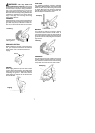
2. Align upper tube groove with triangle on
lower locking sleeve assembly. Push
tubes together until they snap into place.
Alignment Triangle
Upper Tube
Groove
3. Try to pull tubes back apart. If the tubes do
not come apart, they are properly snapped
into place. If the tubes come apart, repeat
step1and push until the tubes snap into
place.
4. Slideupperlockingsleeveassemblyover
lower locking sleeve assembly and tight-
en by turning clockwise.
5. Ensure locking sleeve assembly and
alignmentdecalsappearasillustratedbe-
low.
Alignment decals
WARNING: Failure to completely en-
closeexcess wiresinuppertubeduringassem-
bly of the unitmay resultin damageto thewires
and/or the unit or serious injury to the operator
including electrocution.
WARNING: The upper and lower
tubes must besnapped together, remainper-
manently assembled togetherandthelocking
sleeve assembly must be fully tightened be-
fore and during use to avoid serious injury to
the operator and/or damage to the unit. DO
NOT attempt to disassemble unit after initial
assembly.
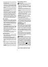
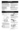
INSTALLATION OF ASSIST HANDLE
1. Place unit on a flat surface.
5. Adjust the handle up and down the tube
and pivot it to a comfortable position;
tighten knob securely.
2. Remove knob and bolt from kit.
3. Push assist handle over the clamp on
the tube (see illustration).
Handle can
be assembled as op
tion 1 or 2 (Shown
Below) depending on the users
preference.
4. Install bolt in handle. Thread knob onto
bolt.
Tube
Assist handle
Trigger
housing
Clamp
ATTACHING EDGE GUIDE AND
SHIELD
WARNING: The shieldmustbeprop-
erly installed. The shield provides partial
protection from the risk of thrown objects to
theoperatorandothers.Yourunit isequipped
with a line limiter blade, which cuts excess
line to the proper length while running. The
line limiter blade (on underside of shield) is
sharp and can cut you.
NOTE: If shield is notproperly installed, dam-
age to unit (including motor failure) will result.
1. Insert edge guide into two holes in shield.
NOTE: Edgeguidemust
bepositionedon
shield prior to installation on motor housing
(see following illustration).
Option 1 Option 2
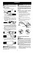
Wire protector
Wires
1. Remove the wire protector from the
tubes and discard.