


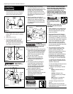
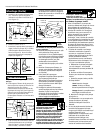
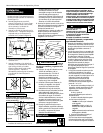
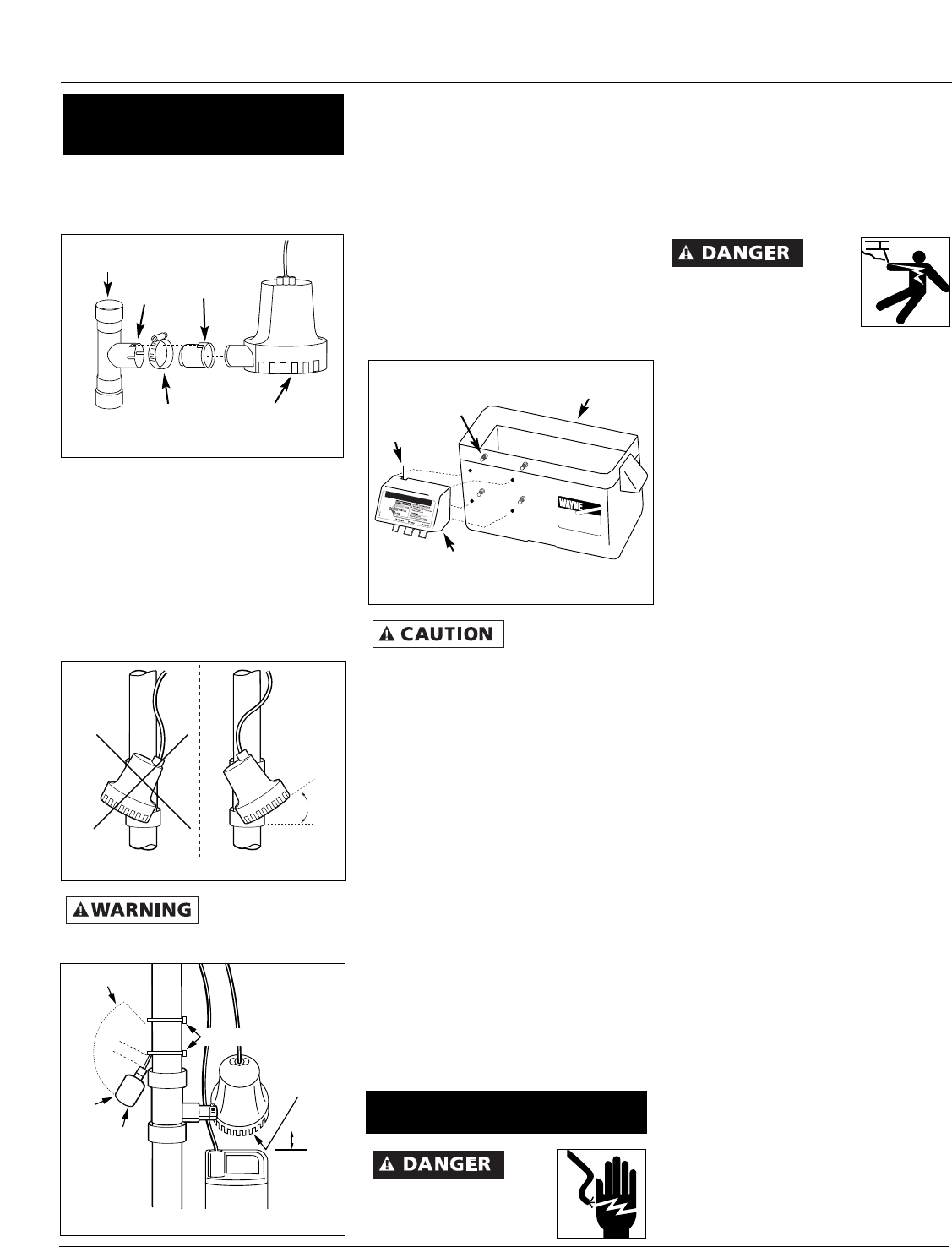
the up direction arrow on the tee; the
notch must be to the top or flapper
valve will not work (see Figure 2).
5. Insert flapper valve into tee. Be sure
locator tab is in the notch in tee (see
Figure 2).
6. Slide clamp onto tee.
7. Insert pump into flapper valve, tilt
pump 30˚. When tilted, side with
power cord should be up (see Figure
3). Tighten clamp around the pump
and flapper valve (see Figure 2).
Pump must be
tilted as shown in
Figure 3 to prevent air locking.
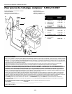
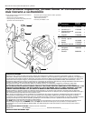
8. The standby pump’s float switch
should be installed so that it will not
activate until the standby pump’s inlet
is under water. Use the wire ties
provided to secure the float switch
(see Figure 4). Make sure power wires
do not interfere with float switch or
pump inlet.
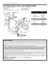
9. Attach control box to the side of
battery box as shown in Figure 5. Place
battery in box, attach red cable to
positive battery post and black cable
to negative post. Put lid on box and
strap closed.
If cables are
reversed, damage to
the control box or battery could result,
and warranty will be void.
10. Place battery box within six feet of the
sump and a 115 VAC separately fused
outlet. The outlet must be protected
by a ground fault circuit interrupter
(GFCI). The area must also be clean,
dry and well-ventilated.
11. Plug the float switch, pump and
charger into the control box. The
connections are marked on the
control box.
12. Test pump operation by filling the
sump with water while the main
pump is unplugged. If the pump
operates properly, plug the charger
into the GFCI protected outlet to
begin charging the battery.
13. Protect electrical cord from sharp
objects, hot surfaces, oil and
chemicals. Avoid kinking the cord and
replace damaged components
immediately.
Always disconnect the
power source before
attempting to install,
2
Operating Instructions And Parts Manual
service, relocate or maintain the pump.
Never touch sump pump, pump motor,
water or discharge piping when pump is
connected to electrical power. Never
handle a pump or pump motor with wet
hands or when standing on wet or damp
surface or in water. Fatal electrical shock
could occur.
Risk of
electrical shock! Use a
GFCI receptacle to reduce
the risk of fatal electrical
shock.
Cutting the cord or plug will void the
warranty and make the pump
inoperable.
1. After installation, the standby pump
will start when the water level rises
above the depth that the primary
pump should start.
2. The control box has a DC charger
designed to shorten the recharging
time of your battery, and to prevent
overcharging. In addition, the control
box has a time delay which keeps the
pump from repeated, short cycles
when it shuts off. This time delay
feature will allow the pump to run
two to three seconds after the switch
reaches the off position.
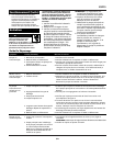
3. The control box contains a multi-
colored indicator light. When AC
power is present, the light will
indicate the charging state, and not
reflect actual battery voltage,
particularly with a defective battery.
In order for the indicator light to
provide an accurate reading, steps
“a” through “d” must be followed.
a. Unplug main AC pump and the
charger--a power off alert tone will
sound for 30 seconds.
b. Lift and release the float switch to
activate the standby pump.
c. When the pump stops, read the
test light:
Green: Indicates battery is
charged.
Yellow: Voltage is low,
indicating battery is partially
charged.
Red: Battery is completely
discharged or defective.
d. Plug in charger and main AC
pump.
When AC power is out, and when
pump has been running, the light will
indicate battery status.
SumpPump
AU X IL IA R Y
BATTERY BACKUP SUMP PUMP
Figure 5
Control
box screw
Battery box bottom
Lead Wires
Control box
Figure 2
Flapper
valve
locator
tab
Notch
Clamp
Standby sump pump
Tee
fitting
30˚
Figure 3
Incorrect
Correct
2 inch
tether
On
Off
Wire ties
Standby
sump
pump
inlet
Float
Switch
Figure 4
1“ min.
Installation
(Continued)
Operation