


Tuning, Chapter 4
WATLOW Series 733/734 Service Manual
21
Tuning
˜
NOTE:
Tune each zone at
a set point above
ambient tempera-
ture.
2. Select a thermal response value using the UP/DOWN keys, 1=slow, 2=me-
dium, and 3=fast. A thermal response value of 2 satisfactorily tunes most
thermal systems.
3. When tuning is complete, the display returns to its previous state and AUtX
reverts to 0. The 733/734 installed appropriate PID tuning parameters and
saved them in the non-volatile memory. If a mechanical relay or contactor
is switching power to the load, a longer cycle time may be desirable to
minimize wear on the mechanical components. Typical life of a mechani-
cal relay is 100,000 cycles at rated load.
To abort auto-tuning, the operator must reset the AUtX parameter to 0, or cycle
power off and on, or enter the Calibration mode. In all cases, aborting auto-tune
restores all values to those previous to auto-tuning.
Manual Tuning
For optimum control performance, tune the Series 733/734 to your thermal system.
The tuning settings here are for a broad spectrum of applications; your system may
have somewhat different requirements. NOTE: This is a slow procedure, taking
from minutes to hours to obtain optimum values.
1. Apply power to the Series 733/734 and enter a set point. Begin with these
Service parameters: Pb = 1, rE = 0.00, rA= 0.00, Ct = 5, CAL = 0, AUt= 0.
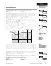
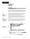
2. Proportional Band Adjustment : Gradually increase Pb until the displayed
temperature stabilizes to a constant value. The process temperature may not
be right on set point because the initial reset value is 0.00 repeats per minute.
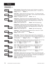
3. Reset Adjustment: Gradually increase rE until the displayed temperature
begins to oscillate or "hunt." Then slowly decrease rE until the temperature
stabilizes again near set point.
4. Cycle Time Adjustment: Set Ct as required. Faster cycle times sometimes
achieve the best system control. However, if a mechanical contactor or
solenoid is switching power to the load, a longer cycle time may be desirable to
minimize wear on the mechanical components. Experiment until the cycle time
is consistent with the quality of control you want. Ct does not effect units with a
process output.
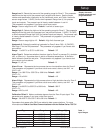
5. Rate Adjustment: Increase rA to 1.00 minute. Raise set point by 20° to 30°F,
or 11° to 17°C, observe the system's approach to set point. If the load tem-
perature overshoots set point, increase rA to 2.00 minutes.
Next raise set point by 20 to 30°F, or 11 to 17°C and watch the approach to the
new set point. If you increase rA too much, approach to set point will be very
sluggish. Repeat as necessary until the system rises to the new set point
without overshooting or approaching the set point too slowly.
6. Calibration Offset Adjustment: You may want your system to control to a
temperature other than the value coming from the input sensor. If so, measure
the difference between that temperature (perhaps at another point in the
system) and the process value showing in the display. Then enter the CAL
offset value you want. Calibration offset adds or subtracts degrees from the
value of the input signal.