


9
MAINTENANCE & REPAIR INSTRUCTIONS
MAINTENANCE SCHEDULE
Perform these required maintenance procedures at the
frequency stated in the table. These procedures should also be
a part of any seasonal tune-up.
NOTE: Some maintenance procedures may require special tools
or skills. If you are unsure about these procedures take
your unit to any non-road engine repair establishment,
individual or authorized service dealer.
NOTE: Maintenance, replacement, or repair of the emission
control devices and system may be performed by any
non-road engine repair establishment, individual or
authorized service dealer.
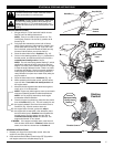
In order to assure peak performance of your engine, inspection
of the engine exhaust port may be necessary after 50 hours of
operation. If you notice lost RPM, poor performance or general
lack of acceleration, this service may be required. If you feel
your engine is in need of this inspection, refer service to any
non-road engine repair establishment, individual or authorized
service dealer for repair. DO NOT attempt to perform this
process yourself as engine damage may result from
contaminants involved in the cleaning process for the port.
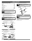
WARNING: To prevent serious injury, never
perform maintenance or repairs with unit running.
Always service and repair a cool unit. Disconnect
the spark plug wire to ensure that the unit cannot
start.
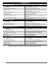
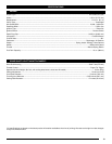
FREQUENCY MAINTENANCE REQUIRED REFER
Before starting Fill fuel tank with fresh fuel Page 3
Every 10 hours Clean and re-oil air filter Page 10
Every 25 hours
Check and clean spark arrestor
Check spark plug condition and gap
Page 10
Page 11
Every 50 hours
Inspect exhaust port and spark arrestor screen for clogging or
obstruction to assure maximum performance levels
Page 10
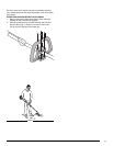
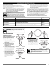
FIXED LINE INSTALLATION
Always use original equipment
manufacturer 0.105 inch
(2.667 mm) replacement line. Lines
other than those specified may
make the engine overheat or fail.
To install the trimming line:
1. Insert each end of the
replacement line into the holes
on either side of retention
hook (Fig. 18).
2. Push the ends through until
they stick out of the sides of
the head (Fig. 19).
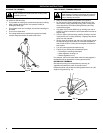
3. Pull the ends through making
sure that the ends are of equal
length and the middle of the
line is centered between the
insertion holes (Fig. 20).
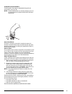
4. If the ends are not of equal
length, push the longer end
back through the head part
way and pull the shorter end to
compensate. Repeat until
both ends are the same
length.
WARNING: Never use metal-reinforced line, wire,
chain, or rope. These can break off and become
dangerous projectiles.
WARNING: Always use the correct line length
when installing trimming line on the unit. If the
two lengths of cutting line are not of equal length,
the unit may develop a vibration.
Fig. 18
Fig. 20
Fig. 19
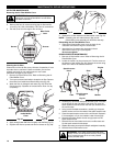
Fig. 21
5. Push the trimmer line until it
lies flat against the cutting
head (Fig. 21). Make sure
the two lengths of cutting line
are of equal length. If they
are not, adjust until they are.