


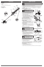


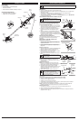
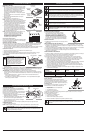


D
-Handle
Switch
Trigger
EZ-Link™
Coupler
C
utting Head Shield
B
attery
L
ock-off
Button
Handle
H
ousing
S
haft Grip
C
utting Head
Battery Charger
Cutting Blades
3
This unit requires assembly.
UNPACKING
• Carefully remove the product and any accessories from the box.
• Inspect the product carefully to make sure no breakage or damage occurred during shipping.
• Do not discard the packing material until you have carefully inspected and satisfactorily operated
the product.
• If any parts are damaged or missing, please call 1-800-828-5500 (U.S.) or 1-800-668-1238
(Canada) for assistance.
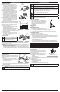
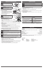
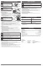
INSTALLING THE CUTTING HEAD SHIELD
Use the following instructions if the cutting head shield is
not installed. Use only the instructions that apply to the
type of shaft and shield equipped with this unit.
1. Place the cutting head shield onto the mount bracket.
Align the holes in the cutting head shield with the holes
in the mount bracket. (Fig. 1)
2. Screw the 2 screws through the mount bracket and into
the cutting head shield until finger tight.
3. Using a #2 Phillips screwdriver, tighten the screws until
the cutting head shield is firmly in place. Tighten the
screws equally. The gap between the mount bracket and
the cutting head shield should be the same on each side.
INSTALLING THE CUTTING BLADES
Refer to Cutting Blade Replacement/Installation in the
Maintenance and Repair Instructions section.
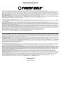
INSTALLING AND ADJUSTING THE D-HANDLE
Installing the D-handle
1. Push the D-handle down onto the boom (Fig. 2), so that
the bolt hole in the D-handle is to the right.
2. Insert the bolt into the hole in the handle. Do not tighten
the bolt completely until after adjusting the D-handle.
Adjusting the D-handle
1. Make sure the bolt is loose enough for the D-handle to
move along the boom.
2. While holding the unit in the operating position (Fig. 11),
move the D-handle to the location that provides the best
grip.
3. Tighten the bolt until the D-handle is secure. (Fig. 2)
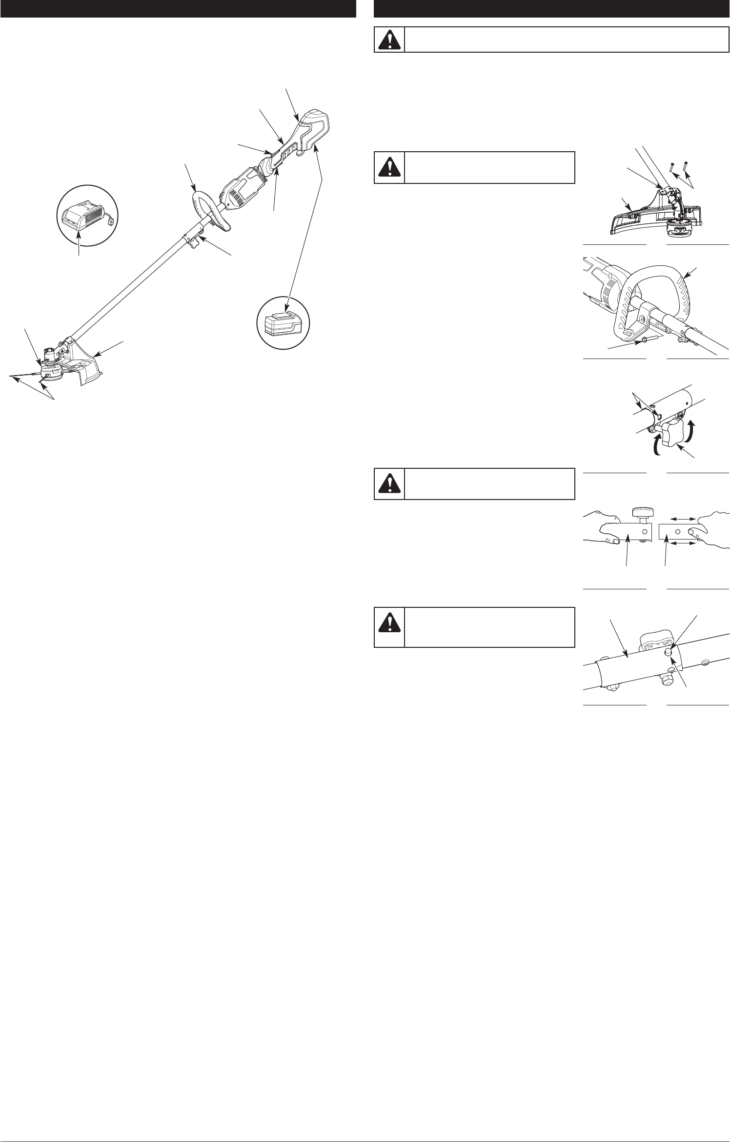
OPERATING THE EZ-LINK SYSTEM
NOTE: To make installing or removing the add-on easier,
place the unit on the ground or on a work bench.
Installing the Add-On
NOTE: Remove the protective cap and gray spacer from the
upper and lower shafts prior to assembling the add-on.
1. Turn the knob counterclockwise to loosen (Fig. 3).
2. While firmly holding the add-on, push it straight into the
EZ-Link coupler (Fig. 4) until the release button snaps
firmly into the primary hole (Fig. 5).
3. Turn the knob clockwise to tighten (Fig. 3).
For decorative edging with the trimmer attachment, lock
the release button into one of the 90° holes (Fig. 3).
Check Flex Shaft Engagement Prior to Using
1. Start the unit. Refer to Starting and Stopping Instructions.
2. Briefly engage and release the trigger.
3. Check that add-on is operating.
4. If the add-on is not operating, remove the add-on and repeat the steps for installing the add-on.
5. Recheck the operation of the add-on attachment.
NOTE: The blades are NOT installed on this product when first removed from packageing. Refer to
Trimmer Blade Replacement/Installation.
Removing the Add-On
1. Turn the knob counterclockwise to loosen (Fig. 3).
2. Press and hold the release button (Fig. 5).
3. While firmly holding the upper shaft housing, pull the add-on out of the EZ-Link coupler (Fig. 4).
KNOW YOUR UNIT ASSEMBLY INSTRUCTIONS
APPLICATIONS
As a trimmer:
• Cutting grass and light weeds
• Edging
• Decorative trimming around trees, fences, etc.
WARNING: Make sure the motor is off and the battery is disconnected before
assembling or disassembling any components.
F
ig. 1
Screws (2)
M
ount
Bracket
C
utting Head
Shield
Fig. 4
L
ower Shaft
Housing
Fig. 3
9
0˚ Edging Holes
(Trimmer Only)
WARNING: To prevent serious personal
injury, never operate the unit without the
cutting head shield in place.
Knob
F
ig. 5
EZ-Link Coupler
TOOLS REQUIRED:
• #2 Phillips screwdriver
• 3/8” Socket
WARNING: To avoid serious personal injury
and damage to the unit, shut the unit off before
removing or installing add-ons.
CAUTION: Before operating this unit, be
sure that the release button is fully snapped
into the primary hole (Fig. 5), and that the knob
(Fig. 3) is securely tightened.
Release Button
U
pper Shaft
Housing
F
ig. 2
D-Handle
Bolt
Primary Hole