


3
ASSEMBLING THE UNIT
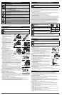
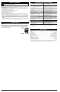
BLOWER ASSEMBLY
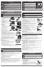
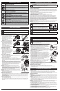
Installing the Upper Blower Tube
1. Align the bump on the end of the upper
blower tube with the bump slot on the bottom
end of the blower outlet (Fig. 1).
2. Insert the upper blower tube into the blower
outlet (Fig. 1).
3. Twist the upper blower tube clockwise until it
locks into place (Fig. 1).
Installing the Lower Blower Tube
1. Align the bump slot on the top end of the lower
blower tube with the bump on the end of the
upper blower tube (Fig. 2).
2. Place the lower blower tube onto the upper
blower tube (Fig. 2).
3. Twist the lower blower tube clockwise until
tight (Fig. 2).
VACUUM ASSEMBLY
Removing the Upper Blower Tube
1. Hold the unit firmly.
2. Insert a flathead screwdriver into the tube
lock. Twist the screwdriver counterclockwise
1/4 turn and hold (Fig. 3).
3. Grasp the upper blower tube and twist it
counterclockwise (Fig. 3).
4. Pull the upper blower tube from the blower
outlet.
Removing the Lower Blower Tube
1. Hold the upper blower tube firmly.
2. Grasp the lower blower tube and twist it counterclockwise until the lower blower
tube unlocks from the upper blower tube.
3. Remove the lower blower tube from the upper blower tube.
Installing the Vacuum Tubes
1. Locate the hole in the impeller door. The door lock tab is recessed in the hole
toward the front of the blower (Fig. 4). Insert a flat head screwdriver, into the hole
and press the door lock tab in and lift the door to release the lock.
2. While holding the impeller door open, align the upper vacuum tube's three (3)
slots with the impeller intake’s three (3) lock tabs (Fig. 5). Insert the upper vacuum
tube into the impeller intake and twist the upper vacuum tube clockwise with both
hands until the lock tabs snap into place (Fig. 6).
3. Align the arrow on the lower vacuum tube with the arrow on the upper vacuum
tube (Fig. 7).
NOTE: The arrows must align properly to install the vacuum tubes correctly.
4. Grasp the lower vacuum tube firmly with both hands and push the lower vacuum
tube into the upper vacuum tube. Turn the lower vacuum tube clockwise until it
snaps into place and locks. The dot on the lower tube aligns with the dot on the
upper tube when properly assembled.
NOTE: Use both hands during this assembly to fit the parts together tightly.
NOTE: The flat area on the upper vacuum tube should face the handle when installed
correctly.
VACUUM BAG ASSEMBLY
Installing the Vacuum Elbow onto the Blower
1. While facing the front of the unit, hold the keyed end of the vacuum elbow in the
left hand and the flared end in the right hand. Align the lock tabs on the keyed end
with the lock tabs on the blower outlet. (Fig. 8)
2. Insert the vacuum elbow into the blower and turn clockwise until it locks into
place. (Fig. 8)
Inserting the Vacuum Elbow into the Bag
1. Locate the small opening in the vacuum bag. Insert the flared end of the vacuum
elbow approximately 4 in. inside the small opening. (Fig. 9)
2. Pull the end of the cinch strap to secure the small opening of the bag around the vacuum elbow. Tighten the cinch
strap so that the bag has limited movement along the elbow, but will not slip off the flared end.
ASSEMBLY INSTRUCTIONS
WARNING:
To prevent serious personal injury, stop the engine and allow the impeller to stop before
attaching or removing tubes.
WARNING:
To prevent serious personal injury or damage to the unit, make sure the blower tubes, or
vacuum tubes and the vacuum bag, are in place before you operate the unit.
SAFETY INFORMATION
Blower Outlet
Bump
Slot
Bump
Fig. 1
Tube Lock
Blower Outlet
Upper Blower Tube
Fig. 3
Upper
Blower Tube
Bump
Bump
Slot
Fig. 2
Upper
Blower
Tube
Lower
Blower
Tube
SYMBOL MEANING
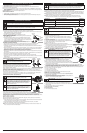
• KEEP BYSTANDERS AWAY
WARNING: Keep all bystanders, especially children and pets, at least 50 feet (15 m)
from the operating area.
• HOT SURFACE
WARNING: Do not touch a hot engine. These parts get extremely hot from
operation and may cause severe burns. When the unit is turned off, the engine will
remain hot for a short time.
• BLOWERS – ROTATING IMPELLER BLADES CAN CAUSE SEVERE INJURY
WARNING: Stop the engine and allow the impeller to stop before installing or
changing tubes, or before cleaning or performing any maintenance.
Impeller
Lock Tabs
Fig. 5
Impeller
Door
Door Lock Tab
Fig. 4
Blower
Outlet
Vacuum
Elbow
Fig. 8
Upper
Vacuum Tube
Lower
Vacuum Tube
Fig. 7
Vacuum
Elbow
Vacuum
Bag
Fig. 9
Upper
Vacuum Tube
Fig. 6
Cinch Strap
4 in.
(10.2 cm)
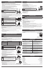
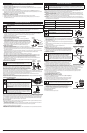
STARTING INSTRUCTIONS
NOTE: When starting the unit, make sure it is not directed at bystanders or loose debris.
1. Mix gas with oil. Fill the fuel tank with fresh fuel/oil mixture. See Oil and Fuel
Mixing Instructions.
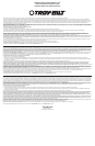
NOTE: There is no need to turn the unit on. The On/Off switch is in the ON ( I )
position at all times (Fig. 10).
2. Fully press and release the primer bulb 10 times, slowly. Some amount of fuel
should be visible in the primer bulb (Fig. 11). If fuel cannot be seen in the bulb,
press and release the bulb until fuel is visible.
3. Move the choke lever to Position 1 (Fig. 11).
NOTE: The unit should be started in idle. Do not squeeze the trigger until step 8 (Fig. 10).
4. Do not squeeze the trigger. Place the unit on a firm, flat surface. Crouch in the
starting position and hold the unit firmly (Fig. 12).
5. Do not squeeze the trigger. Pull the starter rope out until some resistance is felt.
This is usually around 2–4 inches. Pull the starter rope 5 times in a controlled and
steady motion.
6. Do not squeeze the trigger. Move the choke lever to Position 2 (Fig. 11).
7. Do not squeeze the trigger. Pull the starter rope 3-5 times in a controlled and
steady motion to start the engine.
8. Squeeze and hold the trigger, or press down the cruise control (Fig. 10), and allow
the engine to warm up for 30 to 60 seconds.
9. Continue to squeeze the trigger. Move the choke lever to Position 3 (Fig. 11).
10. Continue to squeeze the trigger. Continue warming the engine for an additional
60 seconds. The unit is now ready for use.
IF... The engine does not start, go back to step 2.
IF... The engine fails to start after 2 attempts, move the choke lever to Position 3,
squeeze the trigger, and pull the starter rope 3-8 times in a controlled and steady
motion. The engine should start. If not, repeat.
IF WARM... If the engine is already warm, go back to step 6.
STOPPING INSTRUCTIONS
1. Release the trigger or raise the cruise control to idle the engine.
2. Press and hold the On/Off switch in the OFF (O) position until the engine comes to a complete stop (Fig. 10).
STARTING AND STOPPING INSTRUCTIONS
WARNING: Avoid accidental starting. Make sure you are in the starting position when pulling the starter
rope (Fig. 12). To avoid serious injury, the operator and unit must be in a stable position while starting.
To avoid serious personal injury, make sure that the blower tube is locked in place.
Cruise
Control
On/Off Switch
Fig. 10
Starter Rope
Fig. 12
WARNING:
Operate this unit only in a well-ventilated outdoor area. Carbon monoxide exhaust fumes
can be lethal in a confined area.
Fig. 11
Primer Bulb
Choke Lever
Trigger
Trigger
Starting Position
IF USING THE OPTIONAL ELECTRIC STARTER OR POWER START BIT™ ACCESSORY
NOTE: This Unit Can Use an Electric Start or Power Start Bit™ Optional Accessory!
Please refer to the Electric Starter or Power Start Bit™ operator’s manual for proper use of this feature. (Items Sold
Separately! Please refer to page 4 of this manual about purchasing these accessories.)
STARTING INSTRUCTIONS
NOTE: When starting the unit, make sure it is not directed at bystanders or loose debris.
1. Mix gas with oil. Fill the fuel tank with fresh fuel/oil mixture. See Oil and Fuel Mixing Instructions.
NOTE: There is no need to turn the unit on. The On/Off switch is in the ON ( I ) position at all times (Fig. 10).
2. Fully press and release the primer bulb 10 times, slowly. Some amount of fuel should be visible in the primer bulb
(Fig. 11). If fuel cannot be seen in the bulb, press and release the bulb until fuel is visible.
3. Move the choke lever to Position 1 (Fig. 11).
NOTE: The unit should be started in idle. Do not squeeze the trigger until step 10 (Fig. 10).
4. Do not squeeze the trigger. Place the unit on a firm, flat surface. Crouch in the starting position and hold the unit
firmly (Fig. 12).
5. Do not squeeze the trigger. Insert the electric starter or Power Start Bit™ into the side of the unit (Fig. 22). Refer to the
Operation section of the electric starter or Power Start Bit™ operator’s manual.
6. Do not squeeze the trigger. Press and hold the electric starter or drill’s ON (I) button for 2 seconds.
7. Do not squeeze the trigger. Move the choke lever to Position 2 (Fig. 11).
8. Do not squeeze the trigger. Press and hold the electric starter or drill’s ON (I) button for 2-second intervals until
the unit starts.
9. Do not squeeze the trigger. Remove the electric starter or drill from the unit.
10. Squeeze and hold the trigger, or press down the cruise control (Fig. 10), and allow the engine to warm up for 30 to
60 seconds.
11. Continue to squeeze the trigger. Move the choke lever to Position 3 (Fig. 11).
12. Continue to squeeze the trigger. Continue warming the engine for an additional 60 seconds. The unit is now
ready for use.
IF... The engine does not start, go back to step 2.
IF... The engine fails to start after 2 attempts, move the choke lever to Position 3 and squeeze the trigger. Press and
hold the electric starter or drill ON (I) button for 2-second intervals until the unit starts.
IF WARM... If the engine is already warm, go back to step 7.
STOPPING INSTRUCTIONS
1. Release the trigger or raise the cruise control to idle the engine.
2. Press and hold the On/Off switch in the OFF (O) position until the engine comes to a complete stop (Fig. 10).
OIL AND FUEL MIXING INSTRUCTIONS
Old and/or improperly mixed fuel are the main reasons for the unit not running properly. Be sure to use fresh, clean
unleaded fuel. Follow the instructions carefully for the proper fuel/oil mixture.
Definition of Blended Fuels
Today's fuels are often a blend of gasoline and oxygenates such as ethanol, methanol, or MTBE (ether). Alcohol-
blended fuel absorbs water. As little as 1% water in the fuel can make fuel and oil separate. It forms acids when
stored. When using alcohol-blended fuel, use fresh fuel (less than 30 days old).
Using Blended Fuels
If you choose to use a blended fuel, or its use is unavoidable, follow recommended precautions:
• Always use the fresh fuel mix explained in your operator's manual
• Use the fuel additive STA-BIL® or an equivalent
• Always agitate the fuel mix before fueling the unit
• Drain the tank and run the engine dry before storing the unit
Using Fuel Additives
The bottle of 2-cycle oil that came with your unit contains a fuel additive which will help inhibit corrosion and minimize
the formation of gum deposits. It is recommended that you use our 2-cycle oil with this unit. If unavailable, use a good
2-cycle oil designed for air-cooled engines along with a fuel additive, such as STA-BIL® Gas Stabilizer or an
equivalent. Add 0.8 oz. (23 ml) of fuel additive per gallon of fuel according to the instructions on the container. NEVER
add fuel additives directly to the unit's fuel tank.
Thoroughly mix the proper ratio of 2-cycle engine oil with unleaded gasoline in a separate fuel can. Use a 40:1 fuel/oil
ratio. Do not mix them directly in the engine fuel tank. See the table below for specific gas and oil mixing ratios.
NOTE: One gallon (3.8 liters) of unleaded gasoline mixed with one 3.2 oz. (95 ml) bottle of 2-cycle oil makes a 40:1
fuel/oil ratio.
NOTE: Dispose of the old fuel/oil mix in accordance with federal, state and local regulations.
CAUTION:
For proper engine operation and maximum reliability, pay strict attention to the oil and fuel
mixing instructions on the 2-cycle oil container. Using improperly mixed fuel can severely damage the engine.
OIL AND FUEL INFORMATION
*WARNING: DO NOT USE E85 FUEL IN THIS UNIT.
It has been proven that fuel containing greater than 10% ethanol will likely
damage this engine and void the warranty.
WARNING:
Gasoline is extremely flammable. Ignited vapors may
explode. Always stop the engine and allow it to cool before filling the
fuel tank. Do not smoke while filling the tank. Keep sparks and open
flames at a distance from the area.
WARNING:
Remove fuel cap slowly to avoid injury from fuel spray.
Never operate the unit without the fuel cap securely in place.
OIL AND FUEL INFORMATION
MIXING RATIO - 40:1
UNLEADED GAS* 2-CYCLE OIL
1 GALLON US
(3.8 LITERS)
3.2 FL. OZ.
(95 ml)
1 LITER 25 ml
+
WARNING:
Add fuel in a clean, well ventilated outdoor area. Wipe up any spilled fuel immediately.
Avoid creating a source of ignition for spilled fuel. Do not start the engine until fuel vapors dissipate.
OPERATING INSTRUCTIONS
WARNING: To avoid serious personal injury, wear goggles or safety glasses at all times when
operating this unit. Wear a face mask or dust mask in dusty locations.
WARNING:
To prevent serious personal injury or damage to the unit, make sure the blower tubes, or
vacuum tubes and the vacuum bag, are in place before you operate the unit.
HOLDING THE BLOWER / VACUUM
Before operating the unit, stand in the operating position. Check for the following:
• Operator is wearing proper clothing, such as boots, safety glasses or goggles, ear/hearing protection, gloves, long
pants and long sleeve shirt
• The unit is in good working condition
• The tubes and guards are in place and secure
USING THE CRUISE CONTROL
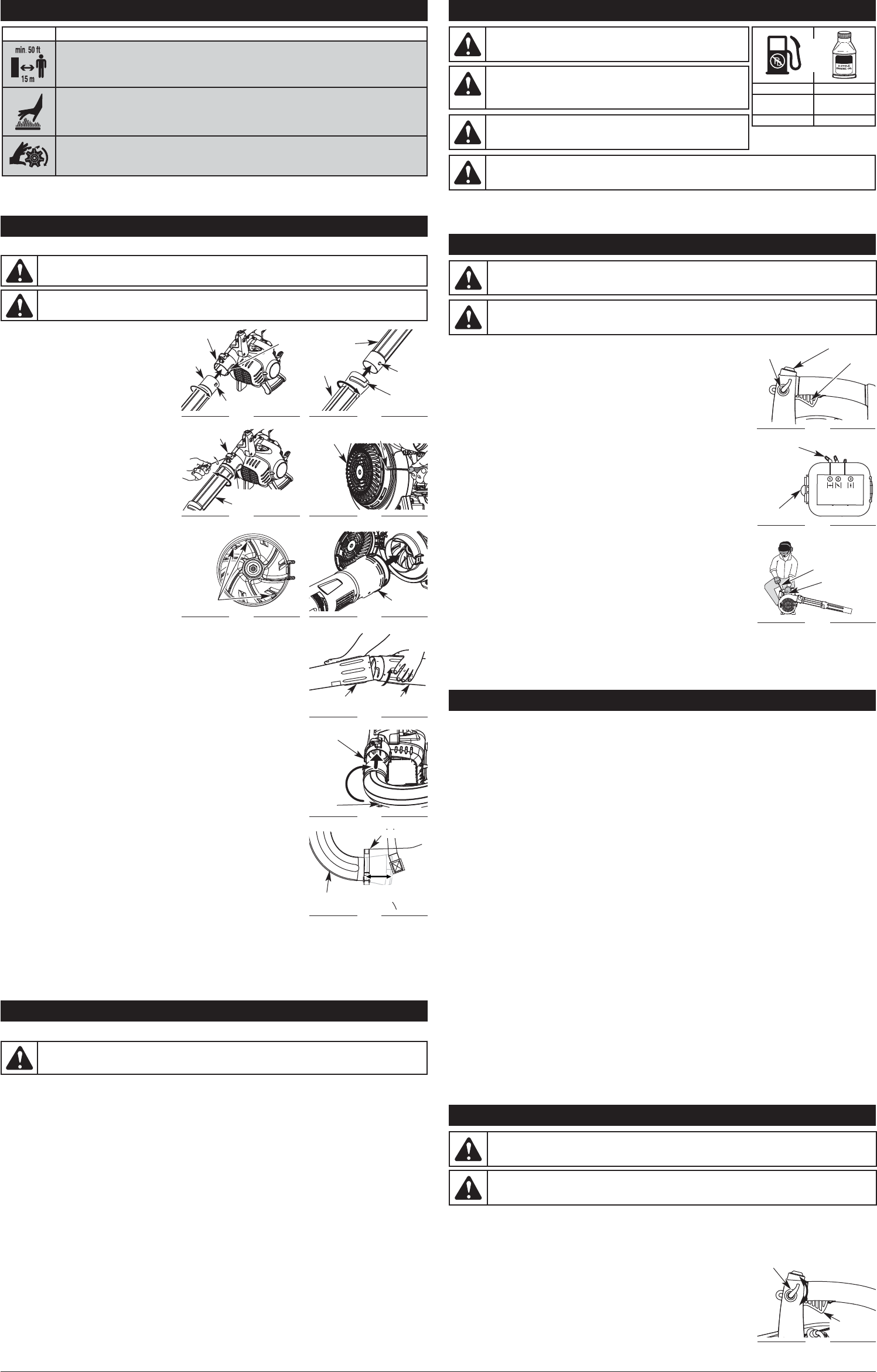
1. Once the engine has started and warmed up, squeeze the trigger to accelerate
the unit as needed (Fig. 13).
2. For longer periods of operation and to eliminate possible finger fatigue, move the
cruise control toward the FAST position to incrementally increase or maintain the
unit’s engine speed (Fig. 13). When the cruise control is pressed, the trigger will
recede into the handle.
3. To decrease engine speed, move the cruise control to the SLOW position and the
trigger will return to idle (Fig. 13).
Fig. 13
SLOW
FAST
Cruise
Control
Trigger
(Idle Position)