


8
OPERATING INSTRUCTIONS
OPERATING THE EZ-LINK™ SYSTEM
The EZ-Link™ system enables the use of these optional add-on
attachments:
Cultivator . . . . . . . . . . . . . . . . . . . . . . . . . . . . . . . . . . . . . TBGC
Edger . . . . . . . . . . . . . . . . . . . . . . . . . . . . . . . . . . . . . . . . TBLE
Hedge Trimmer . . . . . . . . . . . . . . . . . . . . . . . . . . . . . . . . TBAH
Straight Shaft Trimmer . . . . . . . . . . . . . . . . . . . . . . . . . . . TBSS
Turbo Blower . . . . . . . . . . . . . . . . . . . . . . . . . . . . . . . . . . TBTB
Pole Saw . . . . . . . . . . . . . . . . . . . . . . . . . . . . . . . . . . . . . TBPS
Brushcutter . . . . . . . . . . . . . . . . . . . . . . . . . . . . . . . . . . . .TBBC
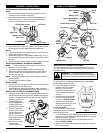
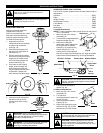
To Install Attachments
NOTE: To make installation easier, place the unit on the ground
or on a workbench.
1. Make sure the unit is turned
completely off.
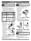
2. Turn the knob counterclockwise to
loosen the coupler (Fig. 20).
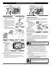
3. While firmly holding the
attachment, push it straight into
the coupler until the release
button (Fig. 21) snaps into the
primary hole (Fig. 21). The
primary hole is on the opposite
side of the coupler from the knob (Fig. 21). Align the release
button with the Guide Recess (Fig. 21) to help installation.
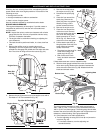
4. Turn the knob clockwise to
tighten (Fig. 22).
To Remove Attachments
1. Make sure the unit is turned
completely off.
2. Turn the knob
counterclockwise to loosen the
coupler (Fig. 20).
3. Press and hold the release
button (Fig. 21).
4. While firmly holding the upper
shaft boom (Fig. 21), pull the
attachment out of the coupler.
Knob
Coupler
Fig. 20
CAUTION: These attachments are to be snapped
into the primary hole only. Using the wrong hole could
lead to personal injury or damage to the unit.
CAUTION: Before operating this unit, be sure
that the release button is fully snapped into the
primary hole (Fig. 21), and that the knob (Fig. 22) is
securely tightened.
Fig. 21
EZ-Link™ Coupler
Release Button
Guide
Recess
Knob
Primary Hole
CAUTION: Lock the release button in the primary
hole (Fig. 15) and securely tighten the knob before
operating this unit.
Fig. 22
Knob
Coupler
Attachment
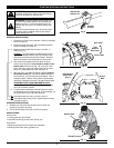
INSTALLING FIXED LINE
Always use original equipment
manufacturer 0.105 inch
(2.667 mm) replacement line. Lines
other than those specified may
make the engine overheat or fail.
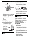
To install the trimming line:
1. Insert each end of the
replacement line into the holes
on either side of retention
hook (Fig. 16).
2. Push the ends through until
they stick out of the sides of
the head (Fig. 17).
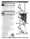
3. Pull the ends through making
sure that the ends are of equal
length and the middle of the
line is centered between the
insertion holes (Fig. 18).
4. If the ends are not of equal
length, push the longer end
back through the head part
way and pull the shorter end to
compensate. Repeat until
both ends are the same length.
5. Push the trimmer line behind
the hook to secure it from
coming loose while running
(Fig. 19).
WARNING: Never use metal-reinforced line, wire,
chain, or rope. These can break off and become
dangerous projectiles.
WARNING: Always use the correct line length when
installing trimming line on the unit.
Fig. 16
Fig. 18
Fig. 17
Fig. 19
WARNING: Before you begin using any
attachment, read and understand the manual that
came with the attachment. Follow all safety
information contained within.
WARNING: To avoid serious personal injury and
damage to the unit, shut the unit off before
removing or installing attachments.
Upper Shaft
Boom
Attachment