


STARTING INSTRUCTIONS
1. Mix fuel with oil. Fill fuel tank with fuel/oil mixture. See Oil and Fuel Mixing
I
nstructions.
2. Fill the fuel tank with fresh, clean fuel mix. Refer to Fueling the Unit.
NOTE: There is no need to turn the unit on. The On/Off Control is in the ON ( I )
p
osition at all times (Fig. 7).
3
. Fully press and release the primer bulb 10 times, slowly. Some amount of fuel
s
hould be visible in the primer bulb and fuel lines (Fig. 8). If fuel can not be seen in
the bulb, press and release the bulb until fuel is visible.
4. Place the choke lever in Position 1 (Fig. 8).
5
. Crouch in the starting position (Fig. 9). Squeeze the throttle control lever. Pull the
starter rope 5 times.
6. Place the choke lever in Position 2 (Fig. 8)
7. Squeeze the throttle control, pull the starter rope in a controlled motion 3 to 5
times to start engine.
8. Keep the throttle squeezed and allow the engine to warm up for 30 to 60 seconds.
9. Continue squeezing the throttle control, move the choke lever to Position 3 (Fig. 8)
a
nd continue warming the engine for an additional 60 seconds. The unit may be
u
sed during this time.
N
OTE: Unit is properly warmed up when engine accelerates without hesitation.
I
F... the engine hesitates, return the choke lever to Position 2 (Fig. 8) and continue
warm-up.
IF... the engine does not start, go back to step 3.
I
F...the engine fails to start after 2 attempts, place the choke lever in Position 3 and squeeze the throttle control. Pull
t
he starter rope out with a controlled and steady motion 3 to 8 times. The engine should start. If not, repeat.
I
F WARM... If the engine is already warm, go back to step 6.
STOPPING INSTRUCTIONS
1. Release the throttle control and allow the engine to cool down by idling.
2. Press and hold the On/Off Control switch in the OFF (O) position until the unit comes to a complete stop (Fig. 7).
•
A
l
w
a
ys
a
g
i
t
a
t
e
t
h
e
f
u
e
l
m
i
x
b
e
f
o
r
e
f
u
e
l
i
n
g
t
h
e
u
n
i
t
•
D
r
a
i
n
t
h
e
t
a
n
k
a
n
d
r
u
n
t
h
e
e
n
g
i
n
e
d
r
y
b
e
f
o
r
e
st
o
r
i
n
g
t
h
e
u
n
i
t
U
S
I
N
G
FU
E
L A
D
D
I
T
I
V
E
S
T
h
e
bo
t
t
l
e
o
f
2
-
c
y
c
l
e
o
i
l
c
o
n
t
a
i
n
s
a
f
u
e
l
a
ddi
t
i
v
e
w
h
i
c
h
w
i
l
l
h
e
l
p
i
n
h
i
bi
t
c
o
r
r
o
s
i
o
n
a
n
d
m
i
n
i
m
i
z
e
t
h
e
f
o
r
m
a
t
i
o
n
o
f
g
u
m
de
po
s
i
t
s
.
I
t
i
s
r
e
c
o
m
m
e
n
de
d
t
o
u
s
e
o
u
r
2
-
c
y
c
l
e
o
i
l
w
i
t
h
t
h
i
s
u
n
i
t
.
If
u
n
a
v
a
ila
b
le
,
u
s
e
a
g
o
o
d
2
-
c
y
c
le
o
il
d
e
s
ig
n
e
d
fo
r
a
ir
-
c
o
o
le
d
e
n
g
in
e
s
a
lo
n
g
wit
h
a
fu
e
l
a
d
d
it
iv
e
,
s
u
c
h
a
s
S
T
A
-
B
IL
Ga
s
S
t
a
b
iliz
e
r
o
r
a
n
e
q
u
iv
a
le
n
t
.
A
d
d
0
.
8
o
z
.
(2
3
m
l)
o
f
fu
e
l
a
d
d
it
iv
e
p
e
r
g
a
llo
n
o
f
fu
e
l
a
c
c
o
r
d
in
g
t
o
t
h
e
in
s
t
ru
c
t
io
n
s
o
n
t
h
e
c
o
n
t
a
in
e
r
.
NE
V
E
R
a
d
d
fu
e
l
a
d
d
it
iv
e
s
d
ir
e
c
t
ly
t
o
t
h
e
u
n
it
’
s
fu
e
l
t
a
n
k
.
T
h
o
r
o
u
g
h
l
y
mi
x
t
h
e
p
r
o
p
e
r
r
a
t
i
o
o
f
2
-
c
yc
l
e
e
n
g
i
n
e
o
i
l
w
i
t
h
u
n
l
e
a
d
e
d
f
u
e
l
i
n
a
se
p
a
r
a
t
e
f
u
e
l
c
a
n
.
U
se
a
4
0
:
1
f
u
e
l
/
o
i
l
r
a
t
i
o
.
D
o
n
o
t
m
i
x
t
h
e
m
d
i
r
e
c
t
l
y
i
n
t
h
e
e
n
g
i
n
e
f
u
e
l
t
a
n
k
.
S
e
e
t
h
e
t
a
b
l
e
f
o
r
sp
e
c
i
f
i
c
g
a
s
a
n
d
o
i
l
m
i
x
i
n
g
r
a
t
i
o
s.
N
O
T
E
:
On
e
gal
l
on
(
3
.
8
l
i
t
er
s
)
of
u
n
l
ead
ed
f
u
el
m
i
x
ed
w
i
t
h
on
e
3
.
2
oz
.
(
9
5
m
l
)
b
ot
t
l
e
of
2
-
cy
cl
e
oi
l
m
ak
es
a
4
0
:
1
f
u
el
/
oi
l
r
at
i
o.
N
O
T
E
:
D
i
sp
o
se
o
f
t
h
e
o
l
d
f
u
e
l
/
o
i
l
m
i
x
i
n
a
c
c
o
r
d
a
n
c
e
t
o
f
e
d
e
r
a
l
,
st
a
t
e
a
n
d
l
o
c
a
l
r
e
g
u
l
a
t
i
o
n
s.
FU
ELI
N
G
TH
E U
N
I
T
1
.
Tu
r
n
u
n
i
t
o
n
i
t
s
si
d
e
,
w
i
t
h
t
h
e
f
u
e
l
c
a
p
f
a
c
i
n
g
u
p
,
a
n
d
r
e
m
o
ve
t
h
e
f
u
e
l
c
a
p
.
2
.
P
l
a
c
e
t
h
e
g
a
s
c
o
n
t
a
i
n
e
r
’
s
sp
o
u
t
i
n
t
o
t
h
e
f
i
l
l
h
o
l
e
o
n
t
h
e
f
u
e
l
t
a
n
k
a
n
d
f
i
l
l
t
h
e
t
a
n
k
.
N
O
T
E
:
D
o
n
o
t
o
ve
r
f
i
l
l
t
h
e
t
a
n
k
.
3
.
Wi
p
e
u
p
a
n
y
g
a
so
l
i
n
e
t
h
a
t
m
a
y
h
a
ve
sp
i
l
l
e
d
.
4
.
R
e
i
n
st
a
l
l
t
h
e
f
u
e
l
c
a
p
.
5
.
Mo
ve
t
h
e
u
n
i
t
a
t
l
e
a
st
3
0
f
t
.
(
9
.
1
m
)
f
r
o
m
t
h
e
f
u
e
l
i
n
g
so
u
r
c
e
a
n
d
si
t
e
b
e
f
o
r
e
st
a
r
t
i
n
g
t
h
e
e
n
g
i
n
e
.
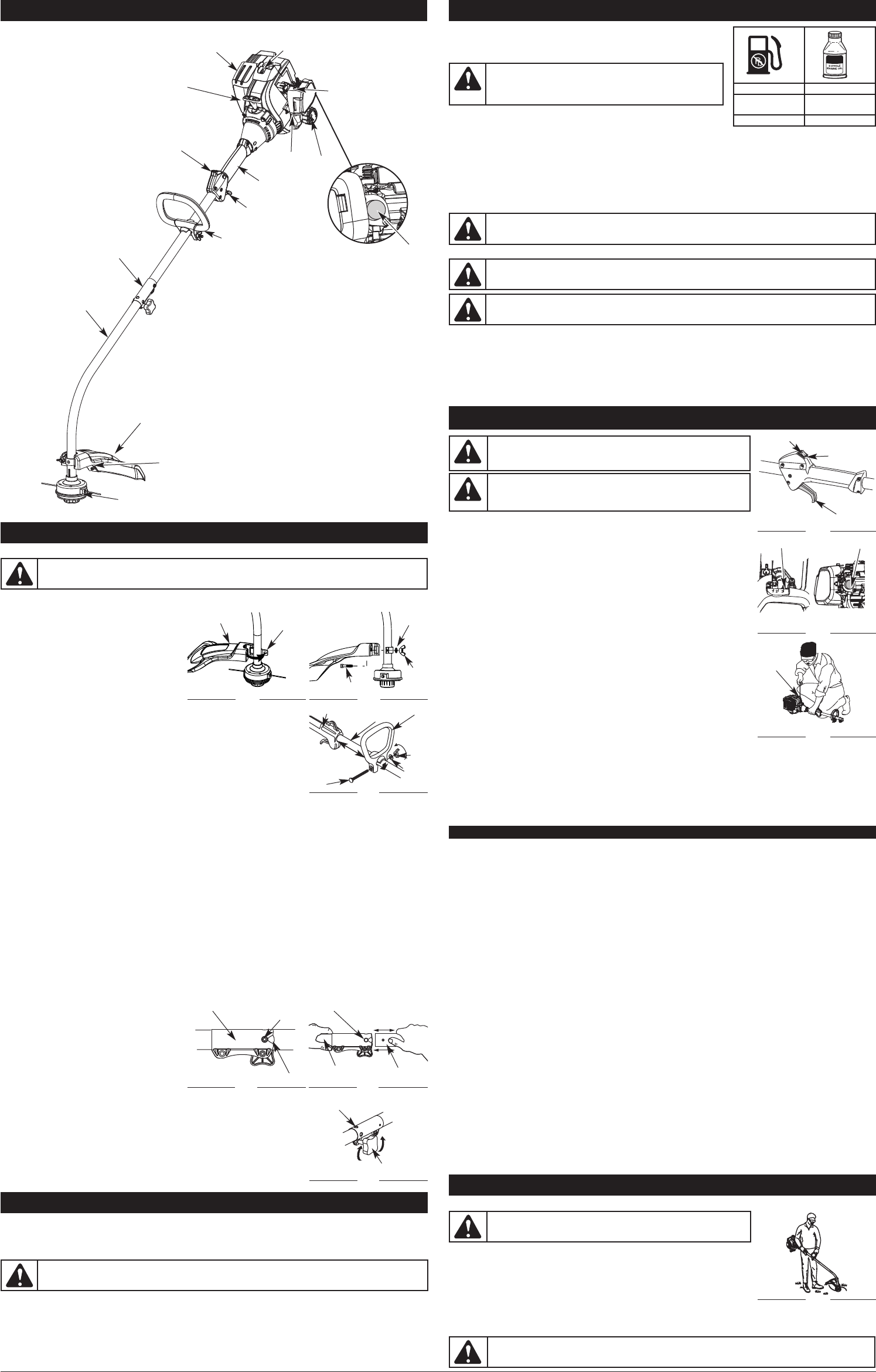
OPERATING INSTRUCTIONS
HOLDING THE UNIT
Before operating the unit, stand in the operating position (Fig. 10). Check for the
following:
• The operator is wearing eye protection and proper clothing
• With a slightly-bent right arm, the operator’s hand is holding the shaft grip
• The operator’s left arm is straight, the left hand holding the D-handle
• The unit is at waist level
• The cutting head is parallel to the ground and easily contacts the grass without the need to bend over
ADJUSTING TRIMMING LINE LENGTH
WARNING:
Always wear eye, hearing, foot and body protection to
reduce the risk of injury when operating this unit.
Fig. 10
OIL AND FUEL MIXING INSTRUCTIONS
Old and/or improperly mixed fuel are the main reasons for the unit not running properly. Be sure to use fresh, clean
unleaded fuel. Follow the instructions carefully for the proper fuel/oil mixture.
DEFINITION OF BLENDED FUELS
Today's fuels are often a blend of gasoline and oxygenates such as ethanol, methanol, or MTBE (ether). Alcohol-
blended fuel absorbs water. As little as 1% water in the fuel can make fuel and oil separate. It forms acids when
stored. When using alcohol-blended fuel, use fresh fuel (less than 30 days old).
USING BLENDED FUELS
If choosing to use a blended fuel, or its use is unavoidable, follow recommended precautions:
• Always use the fresh fuel mix explained in the operator's manual
• Use the fuel additive STA-BIL® or an equivalent
M
IXING RATIO - 40:1
3
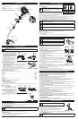
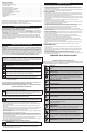
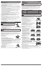
KNOW YOUR UNIT
A
PPLICATIONS
As a trimmer:
• Cutting grass and light weeds.
• Edging
• Decorative trimming around trees,
fences, etc.
Throttle Control
D-Handle
Shaft Grip
A
ir Filter
C
over
S
park Plug
Shaft Housing
S
tarter Rope Grip
Line Cutting
Blade
M
uffler
O
n/Off Control
C
utting Head
Cutting Head Shield
Fuel Cap
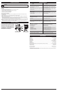
OIL AND FUEL INFORMATION
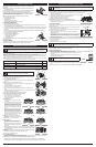
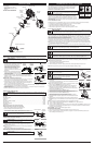
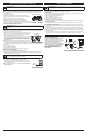
INSTALL CUTTING ATTACHMENT SHIELD
Use the following instructions if the cutting attachment shield on the unit is not installed. Use only the instructions that
a
pply to the type of shaft and shield that the unit is equipped with.
1
.
P
lace the cutting attachment shield onto the shaft
h
ousing. Be sure the guard mounting bracket slides
into the slot on the edge of the cutting shield. Rotate
the shield into place, counterclockwise (Fig. 1). The
h
oles in the guard mounting bracket and cutting
a
ttachment shield will line up.
2
. From inside the cutting attachment shield, push
the square bolt through the hole until the
t
hreaded end protrudes through the guard
m
ounting bracket (Fig. 2).
3
. Put the washer on the bolt, then screw the wing nut onto the bolt and tighten.
I
NSTALL AND ADJUST THE D-HANDLE
1
. Push the D-handle down onto the shaft housing (Fig. 3). The hex bolt hole in the
h
andle should be on the left side.
2
. Insert the the bolt into the hex hole in the handle and push through. Place the
washer on the bolt, then screw the wing nut onto the bolt. Do not tighten until
making the handle adjustment.
3. Rotate the D-handle to place the grip above the top of the shaft housing. Place it
a
minimum of 6 inches (15.24 cm) from the end of the shaft grip.
4
. While holding the unit in the operating position (Fig. 10), move the D-handle to the location that provides the best grip.
5. Tighten the wing nut until the D-handle is secure.
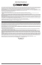
OPERATING THE EZ-LINK™ SYSTEM
T
he EZ-Link™ system enables the use of these optional Add-Ons.
Trimmer. . . . . . . . . . . . . . . . . . . . . . . . . . . . . . . . . . . . . . . . . . . . . . . . . . . . . . . . . . . . . . . . . . . . . . . . . . . . . . . . . . . AF720
Hedge Trimmer*. . . . . . . . . . . . . . . . . . . . . . . . . . . . . . . . . . . . . . . . . . . . . . . . . . . . . . . . . . . . . . . . . . . . . . . . . . . AH720*
Brushcutter* . . . . . . . . . . . . . . . . . . . . . . . . . . . . . . . . . . . . . . . . . . . . . . . . . . . . . . . . . . . . . . . . . . . . . . . . . . . . . . BC720*
Cultivator . . . . . . . . . . . . . . . . . . . . . . . . . . . . . . . . . . . . . . . . . . . . . . . . . . . . . . . . . . . . . . . . . . . . . . . . . . . . . . . . GC720
Edger*. . . . . . . . . . . . . . . . . . . . . . . . . . . . . . . . . . . . . . . . . . . . . . . . . . . . . . . . . . . . . . . . . . . . . . . . . . . . . . . . . . . LE720*
Pole Saw. . . . . . . . . . . . . . . . . . . . . . . . . . . . . . . . . . . . . . . . . . . . . . . . . . . . . . . . . . . . . . . . . . . . . . . . . . . . . . . . . PS720
Straight Shaft Trimmer . . . . . . . . . . . . . . . . . . . . . . . . . . . . . . . . . . . . . . . . . . . . . . . . . . . . . . . . . . . . . . . . . . . . . . SS725
Turbo Blower. . . . . . . . . . . . . . . . . . . . . . . . . . . . . . . . . . . . . . . . . . . . . . . . . . . . . . . . . . . . . . . . . . . . . . . . . . . . . . TB720
* Do NOT use this Add-On with an electric powered unit.
REMOVING THE ADD-ON
1. Turn the knob counterclockwise to loosen (Fig. 6).
2. Press and hold the release button (Fig. 4).
3. While firmly holding the upper shaft housing, pull the lower shaft housing straight out of the EZ-Link™ coupler (Fig.
5).
INSTALLING THE ADD-ON
NOTE: To make installing or removing the add-
on easier, place the unit on the ground
or on a work bench.
1. Turn knob counterclockwise to loosen (Fig. 6).
2. While firmly holding the add-on, push it straight
into the EZ-Link™ coupler (Fig. 5).
NOTE: Aligning the release button with the guide
recess will help installation (Fig. 4).
3. Turn the knob clockwise to tighten (Fig. 6).
For decorative trimming/edging with the line cutting head, lock the release button
into the 90° hole (Fig. 6).
ASSEMBLY INSTRUCTIONS
WARNING:
To prevent serious personal injury, never operate the trimmer without the cutting
a
ttachment shield in place.
Cutting
Shield
M
ount
B
racket
Fig. 1
F
ig. 2
Choke Lever
Primer Bulb
S
quare Bolt
U
NLEADED GAS
2
CYCLE OIL
1
GALLON US
(
3.8 LITERS)
3
.2 FL. OZ.
(
95 ml)
1
LITER
2
5 ml
C
AUTION:
For proper engine operation and maximum
reliability, pay strict attention to the oil and fuel mixing instructions
on the 2-cycle oil container. Using improperly mixed fuel can
severely damage the engine.
WARNING:
Gasoline is extremely flammable. Ignited vapors may explode. Always stop the engine
and allow it to cool before filling the fuel tank. Do not smoke while filling the tank. Keep sparks and open
flames at a distance from the area.
WARNING:
Remove fuel cap slowly to avoid injury from fuel spray. Never operate the unit without the
fuel cap securely in place.
WARNING:
Add fuel in a clean, level and well ventilated outdoor area. Wipe up any spilled fuel immediately.
A
void creating a source of ignition for spilled fuel. Do not start the engine until fuel vapors dissipate.
STARTING AND STOPPING INSTRUCTIONS
WARNING:
Avoid accidental starting. Make sure you are in the
s
tarting position when pulling the starter rope (Fig. 9). To avoid serious
i
njury, the operator and unit must be in astable position while starting.
OFF (O)
ON (I)
Throttle
Control
F
ig. 7
Starter
Rope
S
tarting Position
F
ig. 9
Washer
W
ing
N
ut
WARNING:
It has been proven that fuel containing greater than 10% ethanol will likely damage this engine
and void the warranty.
WARNING:
O
perate this unit in a well-ventilated outdoor area.
C
arbon monoxide exhaust fumes can be lethal in a confined area.
WARNING:
Do not remove or alter the line cutting blade assembly. Excessive line length will cause
premature engine failure and / or unit damage.
Guide Recess
Fig. 4
Release
Button
EZ-Link™ Coupler
Upper Shaft
Housing
Fig. 5
Lower Shaft
Housing
Primary Hole
Knob
Fig. 6
90˚ Edging Hole
(Trimmer Only)
Shaft Grip
Shaft
H
ousing
D-Handle
Tighten
Wing
Nut
Bolt
F
ig. 3
Washer
Minimum
6
inches
(
15.24 cm)
F
ig. 8
Primer Bulb
Choke Lever
H
OW TO START THE UNIT USING THE ELECTRIC STARTER OR POWER START BIT ACCESSORY.
N
OTE: This Unit Can Use an Electric Start or Power Start Bit™ Optional Accessory!
P
lease refer to the Electric Starter or Power Start Bit operator’s manual for proper use of this feature. (Items Sold
Separately! Please refer to page 5 of this manual about purchasing these accessories.)
STARTING INSTRUCTIONS
1. Mix fuel with oil. Fill fuel tank with fuel/oil mixture. See Oil and Fuel Mixing Instructions.
2. Fill the fuel tank with fresh, clean fuel mix. Refer to Fueling the Unit.
NOTE: There is no need to turn the unit on. The On/Off Control is in the ON ( I ) position at all times (Fig. 7).
3. Fully press and release the primer bulb 10 times, slowly. Some amount of fuel should be visible in the primer bulb
(Fig. 8). If fuel cannot be seen in the bulb, press and release the bulb until fuel is visible.
4. Move the choke lever to Position 1 (Fig. 8).
5. Crouch in the starting position (Fig. 9). Place the electric starter or power start bit into the back of the unit. Refer to
the Operation section of the Electric Starter or Power Start Bit operator’s manual.
6. Squeeze the throttle control lever. Press and hold the electric starter or drill ON (I) button for 2 seconds.
7. Move the choke lever to Position 2 (Fig. 8).
8. Squeeze the throttle control lever, press and hold the electric starter or drill ON (I) button for 2-second intervals until
the unit starts.
9. Continue to squeeze the throttle control, remove the electric starter or drill from the unit and allow the engine to
warm up for 30 to 60 seconds.
10.Continue squeezing the throttle control, move the choke lever to Position 3 (Fig. 8) and run the unit for an
additional 60 seconds. The unit may be used during this time
NOTE: Unit is properly warmed up when engine accelerates without hesitation.
IF... the engine hesitates, return the choke lever to Position 2 (Fig. 8) and continue warm-up.
IF... the engine does not start, go back to step 3.
IF... the engine fails to start after 2 attempts, place the choke lever in Position 3 and squeeze the throttle control. Press
and hold the electric starter or drill ON (I) button for 2-second intervals until the unit starts.
IF WARM... If the engine is already warm, start the unit with the blue choker lever in Position 2. After the unit starts,
move the blue choker lever to Position 3.
STOPPING INSTRUCTIONS
1. Release the throttle control and allow the engine to cool down by idling.
2. Press and hold the On/Off Control switch in the OFF (O) position until the unit comes to a complete stop (Fig. 7).
IF USING THE OPTIONAL ELECTRIC STARTER OR POWER START BIT™ ACCESSORY
OIL AND FUEL INFORMATION
EZ-Link™
NO ASSEMBLY TOOLS REQUIRED