


13
MAINTENANCE SCHEDULE
Perform these required maintenance procedures at the frequency
stated in the table. These procedures should also be a part of any
seasonal tune-up.
NOTE: Some maintenance procedures may require special tools or
skills. If you are unsure about these procedures, take the unit to
an MTD authorized service dealer.
NOTE: Maintenance, replacement, or repair of the emission control
devices and system may be performed by an MTD authorized
service dealer.
NOTE: Please read the California/EPA statement that came with the
unit for a complete listing of terms and coverage for the
emissions control devices, such as the spark arrestor, muffler,
carburetor, etc.
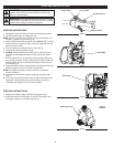
WARNING:
To prevent serious injury, never perform
maintenance or repairs while the unit is running. Always
allow the unit to cool before servicing or repairing the unit.
Disconnect the spark plug wire to prevent the unit from
starting accidentally.
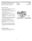
MAINTENANCE
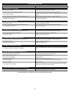
FREQUENCY MAINTENANCE REQUIRED
Every 10 hours • Clean and re-oil the air filter. Refer to
Maintaining the Air Filter.
Every 25 hours • Check the spark plug condition and gap.
Refer to Maintaining the Spark Plug.
REPLACING THE TRIMMING LINE
Only use the trimming line described in the Specifications section.
Other types of trimming line may cause the unit to overheat or fail.
NOTE: Always use the correct line length when installing trimming
line. The line may not release properly if the line is too long.
NOTE: The outer spool will remain attached to the unit.
Installing New Trimming Line
1. If necessary, remove any old trimming line and/or obstructions
from the cutting head. Refer to Removing Old Trimming Line and
Obstructions.
2. Cut one 20 foot (6 m) length of new trimming line.
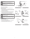
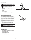
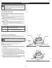
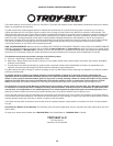
3. Turn the bump knob clockwise to align the arrows (Fig. 16).
4. Insert the new trimming line into the entry eyelet (Fig. 16). Push
the line through the cutting head until a few inches protrude from
the exit eyelet. Pull the protruding line until approximately 10 feet
(3 m) of line extends from each side of the cutting head. Make
sure the line lengths on each side are equal.
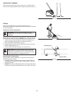
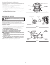
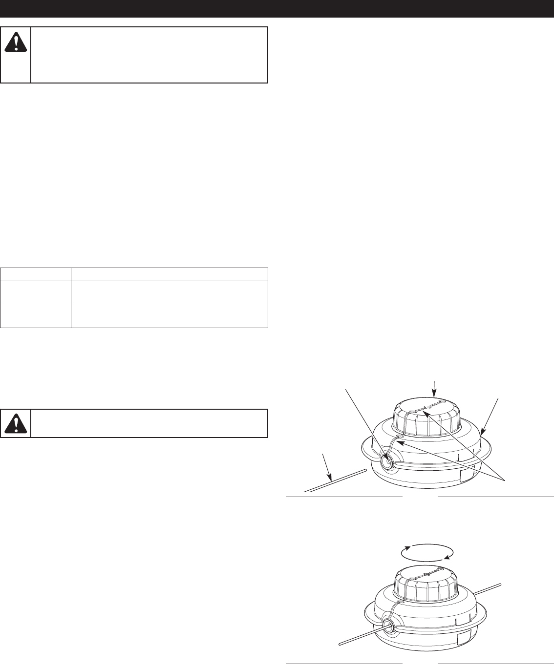
5. Turn the bump knob clockwise to wind the line until about 5 inches
(12.7 cm) protrude from each side of the cutting head (Fig. 17). DO
NOT push the bump knob down while winding the line.
WARNING:
Never use metal-reinforced line, wire, chain or
rope. These can break off and become dangerous projectiles.
Fig. 16
Bump Knob
Entry Eyelet
Exit Eyelet
Trimming
Line
Arrows
Fig. 17