


Assembly
Handle
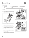
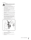
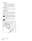
Place the shift lever in the Forward-6 position
Observe the lower rear area of the snow thrower to be sure
both cables are aligned with roller guides before pivoting
the handle upward. See Fig. 3-1.
NOTE: Make certain the upper ends of each cable are
seated properly in its bracket.
Secure the handle by tightening the plastic knob located
on both the left and right sides of the handle. Remove
and discard any rubber bands, if present. They are for
packaging purposes only.
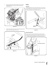
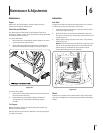
Chute Assembly
Remove wing nut and hex screw from chute control
assembly and clevis pin and cotter pin from chute support
bracket. Position the chute assembly (forward-facing) over
the chute base. See Fig. 3-2.
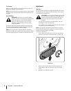
Place chute assembly onto chute base and secure chute
control assembly to chute support bracket with clevis pin
and cotter pin removed earlier. See See Fig. 3-3.
1.
2.
3.
1.
2.
Figure 3-3
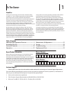
Contents of Carton
One Snow Thrower• Two Replacement Auger Shear Pins• One Product Registration Card•
One Snow Thrower Operator’s
Manual
• One Tecumseh Engine Operator’s
Manual
•
Figure 3-1
1
1
2
Figure 3-2
Assembly & Set-Up
3
6