


Section 7— Service
30
Place the belt around the idler pulleys removed in step 3
hardware and tighten the flange lock nut to secure the
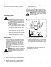
7. Route the belt as shown in Figure 7-8 and then reinstall the
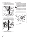
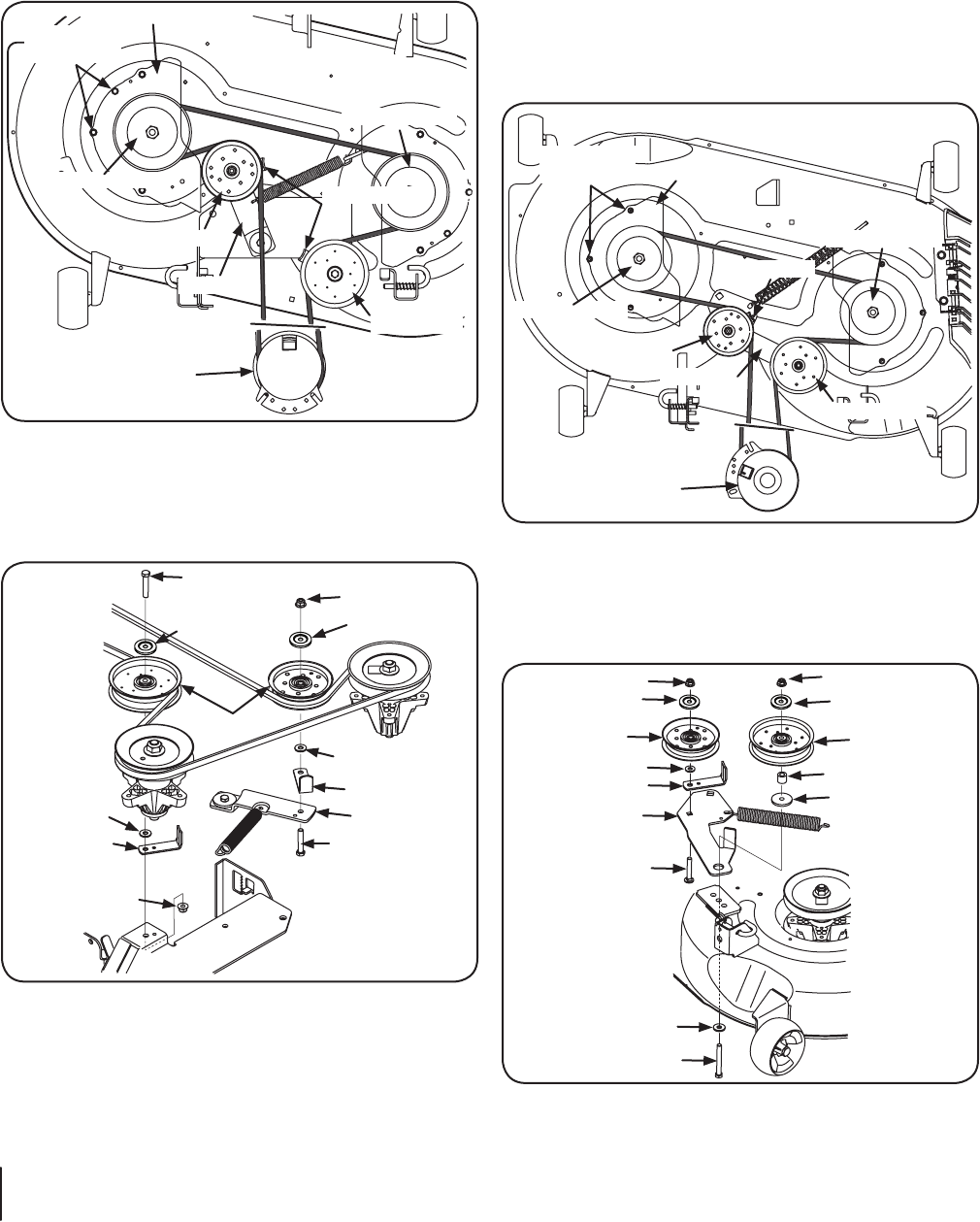
46” Deck
Remove the deck from beneath the tractor, (refer to Deck
Removal on page 27).
2. Remove the hex washer screws securing the belt covers to
PTO Pulley
Idler Pulley
Idler Pulley
Belt Cover
Hex Washer
Screws
Belt Guard
Spindle Pulley
Spindle Pulley
Idler Arm
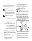
Figure 7-10
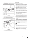
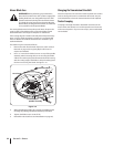
3. Remove the two idler pulleys by removing the hex screws
and flange lock nuts that secure them to the deck and the
when removing the hex screw and flange lock nut.
Pulley Cap
Washer
Flange Lock Nut
Flange Lock Nut
Pulley Cap
Idler Pulley
Idler Pulley
Belt Guard
Spacer
Shoulder Spacer
Idler Arm
Hex Screw
Flat Washer
Hex Screw
Figure 7-11
NOTE: Take note of the position of the belt guard to ensure
they are properly re-installed.
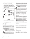
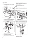
Replacing the Belt
42” Deck
Remove the deck from beneath the tractor, (refer to Deck
Removal on page 27).
2. Remove the hex washer screws securing the belt covers to
the deck. See Figure 7-8.
Hex Washer
Screws
Belt Cover
Belt Guards
Idler Pulley
Idler Pulley
PTO Pulley
Spindle Pulley
Spindle Pulley
Idler Arm
Figure 7-8
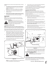
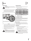
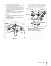
3. Remove the two idler pulleys by removing the hex screws
and flange lock nuts that secure them to the deck and the
when removing the hex screw and flange lock nut.
Hex Screw
Hex Screw
Pulley Cap Pulley Cap
Washer
Belt Guard
Belt Guard
Washer
Idler Arm
Flange Lock Nut
Flange Lock Nut
Idler Pulleys
Figure 7-9
NOTE: Take note of the position of the belt guards to
ensure they are properly re-installed.
Remove the belt from the spindle pulleys.
5. Install the new belt around the spindle pulleys as shown
and reinstall the belt covers. See Figure 7-8.