


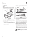


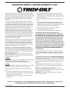
Belt Replacement
Drive Belt
NOTE: To aid in reassembly, note the orientation of the drive belt
on the two idler pulleys and the engine flywheel pulley prior to
performing the following steps. Refer to Fig. 7-1.
The edger drive belt is subject to wear and should be replaced if
any signs of cracking, shredding or rotting are present. To replace
the belt, proceed as follows:
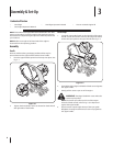
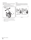
Working in front of the edger, loosen the flange lock nut
on top of frame, allowing the idler pulley assembly to pivot
slightly out from the frame. See Fig. 7-1.
With your other hand, carefully reach under the rear of
the edger and remove the belt from around the engine
flywheel pulley. See Fig. 7-1.
1.
2.
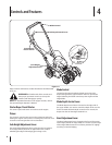
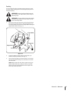
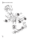
Remove the spindle sheaves belt guard by removing the
two self-tapping screws which secure it to the blade plate
assembly. See Fig. 7-2.
Carefully remove the belt from off of the pulleys, again
making sure to note the orientation of the belt. Discard the
belt. See Fig. 7-2.
5. Working from the front of the edger, place the belt
onto the spindle sheaves, route it back onto the two idler
pulleys, and then place it onto the engine flywheel pulley.
NOTE: Make certain that the “V” side of the belt is seated
into the top pulley and the flat side of the belt is seated
into the bottom pulley. See Fig. 7-2.
Reinstall the spindle sheaves belt guard with the self
tapping screws removed earlier.
Make certain that the drive belt is on the engine flywheel
pulley and idler pulleys, and retighten the flange lock nut
on the top of the frame.
NOTE: Make certain that the drive belt is seated correctly
and that it is riding smoothly on the spindle sheaves and is
not pinched between them. Repeat the first three steps if
the belt is pinched.
WARNING! Never operate the edger without the
spindle sheaves belt guard in place.
3.
4.
5.
6.
7.
Flange
Luck Nut
Engine
Flywheel
Pulley
Figure 7-1
Engine Flywheel Pulley
Belt Guard
Figure 7-2
Service
7
14