


Storing Your Tiller
When your tiller won’t be used during the
off-season, prepare it for storage with the
following steps:
1. Clean the tiller and engine.
2. Do routine tiller lubrication and check
for loose hardware.
3. Protect the engine from deterioration
or damage by referring to the engine
storage instructions in your engine
manual literature.
4. When engine is still warm, drain oil
from engine crankcase. Refill with fresh
motor oil.
5. Protect internal cylinder against rust by
removing spark plug and pouring one
ounce of clean engine oil into spark plug
hole. Then slowly pull out recoil start
rope 2 or 3 times to distribute oil inter-
nally. Replace spark plug, but do not
reconnect plug wire. Pull rope until resis-
tance is felt — let rope rewind.
6. Charge battery (electric start option).
Store battery in cool, dry location.
7. Move Wheels/Tines/PTO Drive Lever to
NEUTRAL position. Keep tiller in a clean,
dry area.
8. Never store tiller with fuel in fuel tank
in an
enclosed area where gas fumes
could reach an open flame or spark, or
where ignition sources are present (space
heaters, hot water heaters, furnaces, etc.).
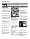
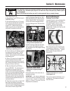
Inspecting Forward Interlock
Wiring System
Check the Forward Interlock wiring
system every ten (10) operating hours,
for tight connections and to see that the
insulation on the wires is unbroken (to
prevent the system from shorting out).
1. Check insulated wire harness from
lower ends of handlebars to wire harness
connector on top, right side of transmis-
sion cover. Be sure connector is secure.
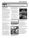
2. Check insulated tubing from connector
to cast iron motor mount/belt shroud.
3. Check the wire leading from the tubing
over to the switch assembly mounted on
top of the tab on the cast iron motor
mount–belt shroud. Also check the
second wire that leads to the throttle
cable mounting bracket on the right side,
forward portion of the engine.
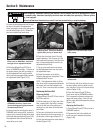
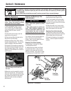
Testing the Forward
Interlock Wiring System
The wiring circuit for the Forward
Interlock Safety System is designed to
ground out the engine’s ignition system.
There are three switches in the circuit
which, when open, let the engine run.
One switch is on the neutral plunger tab
of the cast iron motor mount. This switch
is open whenever the Wheels/Tines/PTO
Drive Lever is in NEUTRAL or REVERSE
positions. The other two switches are
located inside the handlebars, directly
above the two Forward Interlock Levers.
The switches are wired so when squeezed
(open) the engine will run. There is a
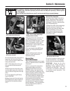
fourth switch located in the wiring
harness connector on the top, right side
of the transmission cover. It warns you if
the connection is not mated by not letting
the engine run while the Wheels/Tines/PTO
Drive Lever is in FORWARD.
1. A broken or disconnected wire could
let the engine run without you having to
press one of the Forward Interlock Levers.
2. A bare wire touching tiller or engine
metal could ground out the engine’s
ignition.
3. A switch that has failed allows the
engine to run. Or it may prevent the
engine from running.
Refer to the
Troubleshooting section if
your Forward Interlock Safety System is
not operating correctly.
Before inspecting, cleaning or servicing the machine, shut off engine, wait for all moving parts to come
to a complete stop, disconnect spark plug wire and move wire away from spark plug. Remove ignition
key, if so equipped.
Failure to follow these instructions can result in serious personal injury or property damage.
WARNING
Section 5: Maintenance
40