


6
3
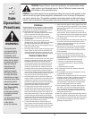
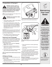
Setup and
Adjustment
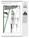
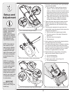
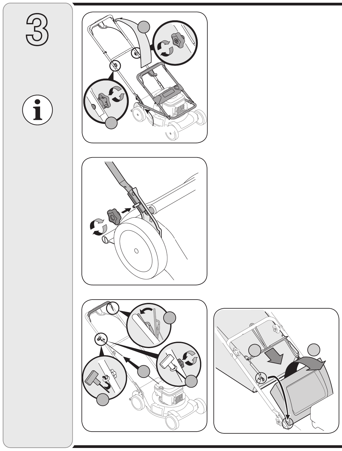
1. Remove any packing material which may be between
upper and lower handles.
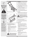
a. Pull up and back on upper handle as shown in
Figure 3-1. Do not crimp cable while lifting the
handle up. Remove star knobs from handle mount-
ing brackets and secure the lower handle onto the
handle brackets by placing the lower hole of the
lower handle onto the pins of the handle brackets.
b. Tighten star knobs securing upper handle to lower
handle. See Figure 3-1. Make sure that each
carriage bolt is seated properly in the handle.
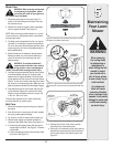
2. Tighten star knobs securing lower handle to handle
brackets. See Figure 3-2. Make certain the lower
handle is seated securely into the handle mounting
brackets.
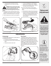
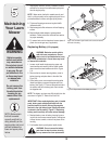
3. The rope guide is attached to the right side of the
upper handle. Loosen the wing nut which secures the
rope guide. See Figure 3-3.
a. Hold the blade control against upper handle.
b. Pull starter rope out of the engine. Release the
blade control.
c. Slip starter rope into rope guide.
d. Tighten wing nut.
4. Secure cables to the lower handle using the cable tie.
Pull cable tie tight and cut off excess.
5. To assemble the grass catcher (if needed), place bag
over frame with the black plastic side at the bottom.
Slip plastic channel over hooks on frame. All channels
except for center top of bag attach from the outside.
The center of bag attaches from the inside.
6. Before attaching the grass catcher, the mulching
baffle must be removed. Refer to Figure 3-5.
a. Lift rear discharge door.
b. Remove mulching baffle.
7. To attach grass catcher, refer to Figure 3-4.
a. Lift rear discharge door.
NOTE: Stand behind
the mower as if you
were going to operate
it. Your right hand cor-
responds to the right
side of the mower; your
left hand corresponds
to the left side of the
mower.
NOTE: For shipping
purposes your mower
is set with the wheels
in a low cutting height
position. For best
results raise the cutting
position until it is deter-
mined which height is
best for your lawn, refer
to Adjustment section
for instructions.
IMPORTANT
DO NOT crimp the
cables when lifting the
handle up.
Figure 3-1: Unfold handle and tighten hardware.
Figure 3-2: Secure handle to handle mounting brackets.
Figure 3-3: Pull recoil starter through rope guide and tighten.
Figure 3-4: Lift discharge door and place grass catcher on rod.
B
A
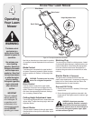
NOTE: This Operator’s
Manual covers several
models. Lawn Mower
features vary by
model. Not all features
discussed (or engines
pictured) in this manual
are applicable to all
Lawn Mower models.
Handle Mounting Bracket
A
B
A
C
D
B