


Assembly & Set-Up
3
9
Tractor Set-Up
Tools Required:
• 3/8-inchwrench(oradjustablewrench)
• 7⁄16-inchwrench(oradjustablewrench)
• 9⁄16-inchwrench(oradjustablewrench)
• 3⁄4-inchwrench(oradjustablewrench)
• 1/2-inchsocketwrench
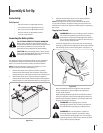
Connecting the Battery Cables
CALIFORNIA PROPOSITION 65 WARNING:
Batteryposts,terminals,andrelatedaccessories
containleadandleadcompounds,chemicalsknown
totheStateofCaliforniatocausecancerand
reproductiveharm.Washhandsafterhandling.
CAUTION: Whenattachingbatterycables,always
connectthePOSITIVE(Red)wiretoitsterminalfirst,
followedbytheNEGATIVE(Black)wire.
Forshippingreasons,bothbatterycablesonyourequipment
mayhavebeenleftdisconnectedfromtheterminalsatthe
factory.Toconnectthebatterycables,proceedasfollows:
NOTE: ThepositivebatteryterminalismarkedPos.(+).The
negativebatteryterminalismarkedNeg.(–).
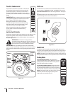
1. Removetheplasticcover,ifpresent,fromthepositive
batteryterminalandattachtheredcabletothepositive
batteryterminal(+)withtheboltandhexnut.SeeFigure3-1.
2.
Removetheplasticcover,ifpresent,fromthenegative
batteryterminalandattachtheblackcabletothenegative
batteryterminal(–)withtheboltandhexnut.SeeFigure3-1.
Figure 3-1
3. Positiontheredrubberbootoverthepositivebattery
terminaltohelpprotectitfromcorrosion.
NOTE: Ifthebatteryisputintoserviceafterthedateshown
ontop/sideofbattery,chargethebatteryasinstructedinthe
MaintenancesectionyourOperator’sManualpriortooperating
thetractor.
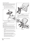
Shipping Brace Removal
WARNING! Makesuretheridingmower’sengineis
off,removetheignitionkey,andsettheparking
brakebeforeremovingtheshippingbrace.Referto
theControlsandFeaturessectionforinstructionson
howtosettheparkingbrake.
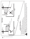
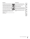
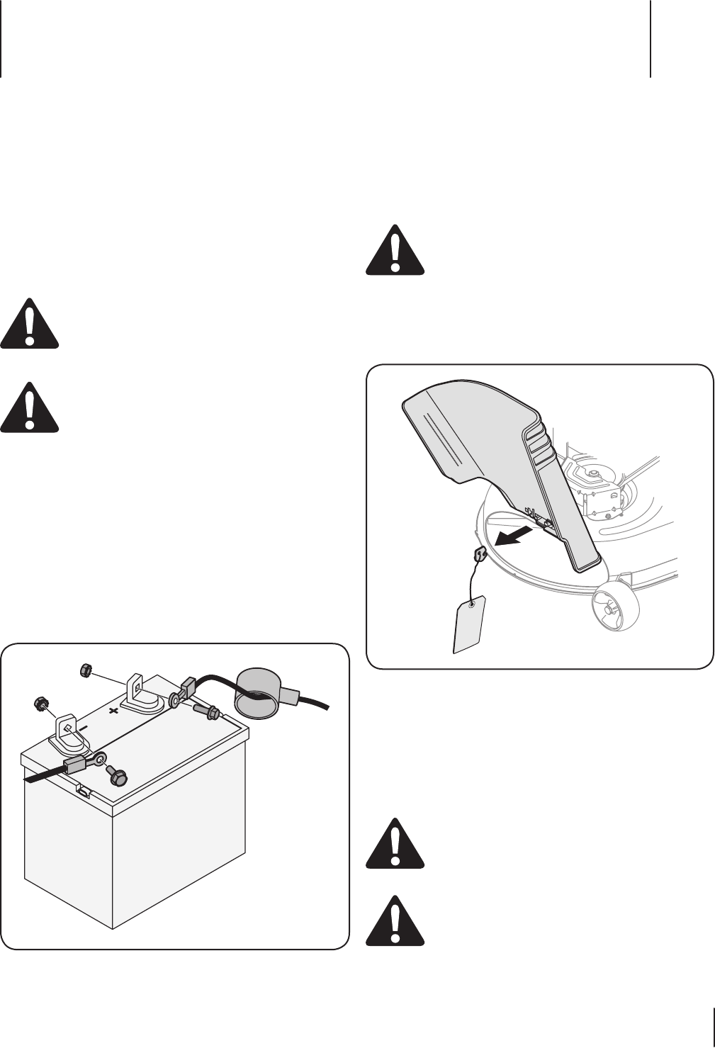
• Locatetheshippingbrace,ifpresent,andaccompanying
warningtagfoundontherightsideofthemower,between
thedischargechuteandthecuttingdeck.SeeFigure3-2.
Figure 3-2
• Placethedeckliftleverinthehighestcuttingposition.
RefertoSettingtheCuttingHeightintheOperation
sectionofthismanual.
• Whilepushingthedischargechutetowardsthemachine
withyourlefthand,removetheshippingbracewithyour
righthandbygraspingitbetweenyourthumbandindex
fingerandrotatingitclockwise.
WARNING! Theshippingbrace,usedfor
packagingpurposesonly,mustberemovedand
discardedbeforeoperatingyourridingmower.
WARNING! Themowingdeckiscapableof
throwingobjects.Failuretooperatetheriding
mowerwithoutthedischargecoverintheproper
operatingpositioncouldresultinseriouspersonal
injuryand/orpropertydamage.