


WARNING! To prevent personal injury or property
damage, do not start the engine until all assembly
steps are complete and you have read and
understand the safety and operating instructions in
this manual.
Recommended Tools for Assembly
⁄” open-end wrench
⁄” open-end wrench
⁄” open-end wrench
Scissors (to trim plastic ties)
Ruler (for belt tension check)
Block of wood (to support tiller when removing wheels)
Tire pressure gauge (for models with pneumatic tires)
Clean oil funnel
Motor oil. Refer to the Engine Operator’s Manual for oil
specifications and quantity required.
Contents of Hardware pack
Hex Screw, ⁄-18 x 1-⁄”
Hex Screw, ⁄-16 x ⁄”
Flat Washer, ⁄”
Split Lock Washer, ⁄”
Hex Nut, ⁄”-18
Hex Locknut, ⁄”-16
Assembly
Unpacking Instructions
NOTE: While unpacking, do not severely bend any of the control
cables.
The tiller weighs approximately 133 lbs. Do not attempt to
remove it from the shipping platform until instructed to do
so in these assembly steps.
Remove any packaging material from the carton. Remove
any staples from the bottom of the carton and remove the
carton from the shipping platform.
Remove all unassembled parts and the separate hardware
pack from the carton. Check that you have the items listed
in the Contents of Carton list (contact your local dealer or
the factory if items are missing or damaged).
•
•
•
•
•
•
•
•
•
•
•
•
•
•
•
1.
2.
3.
4.
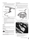
Handle
NOTE: All references to the right or left side of the tiller are from
the operators positon.
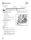
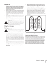
Loosely attach the legs of the handlebar support to the
inner sides of the tiller frame using two ⁄”-16 x ⁄” hex
head screws, ⁄” flat washers, and ⁄”-16 hex locknuts. See
Fig. 3-1.
1.
Contents of Carton
One Tiller • One Handlebar Support• One Handlebar Assembly•
One Hardware Pack• One Operator’s Manual• One Engine Operator’s Manual•
Hex Screw
Flat Washer
Locknut
Figure 3-1
Assembly & Set-Up
3
6