


6
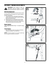
SECTION 2: ASSEMBLING YOUR SNOW THROWER
NOTE: References to right or left side of the snow
thrower are determined from behind the unit in the
operating position (standing directly behind the snow
thrower, facing the handle panel).
IMPORTANT:
Two replacement auger shear pins are
included with this manual (or stowed in the plastic
handle panel). Refer to Augers on page 19 for more
information regarding shear pin replacement.
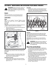
CAUTION: Prior to operating your snow
thrower, refer to Auger Control Test on page 11.
Read and follow all instructions carefully and
perform all adjustments to verify your snow
thrower is operating safely and properly.
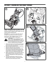
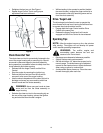
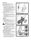
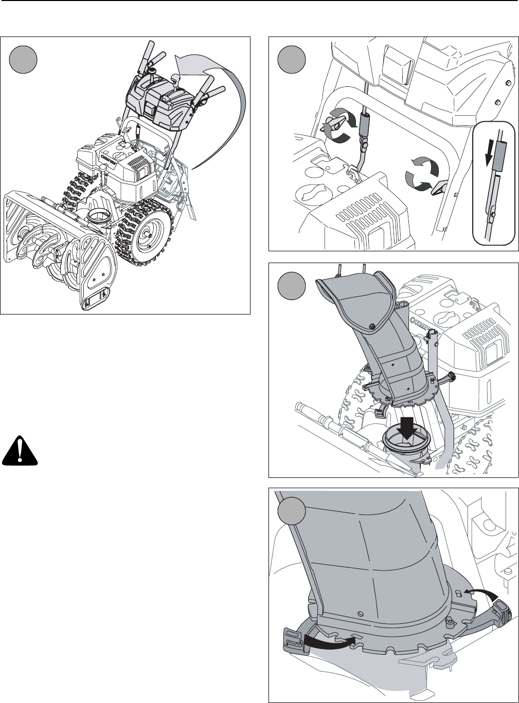
1. Observe the lower rear area of the snow thrower to
be sure both cables are aligned with roller guides
before pivoting the handle upward.
2. Secure the upper shift rod to the lower shift rod by
sliding the connector sleeve downward.
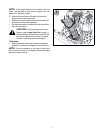
• Secure the handle by tightening the plastic wing
knob located on both the left and right sides of the
handle. Remove and discard any rubber bands, if
present. They are for packaging purposes only.
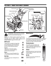
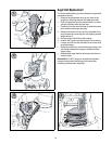
3. Apply a light lubricant (i.e. 3-in-1 oil) to the rim/lip of
the chute base (and the underside of the chute
assembly) and position the chute assembly over
the base.
4. Close the flange keepers to secure the chute
assembly to the chute base. The flange keepers
will click into place when properly secure.
2
3
4
1