


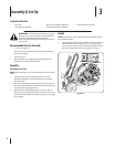
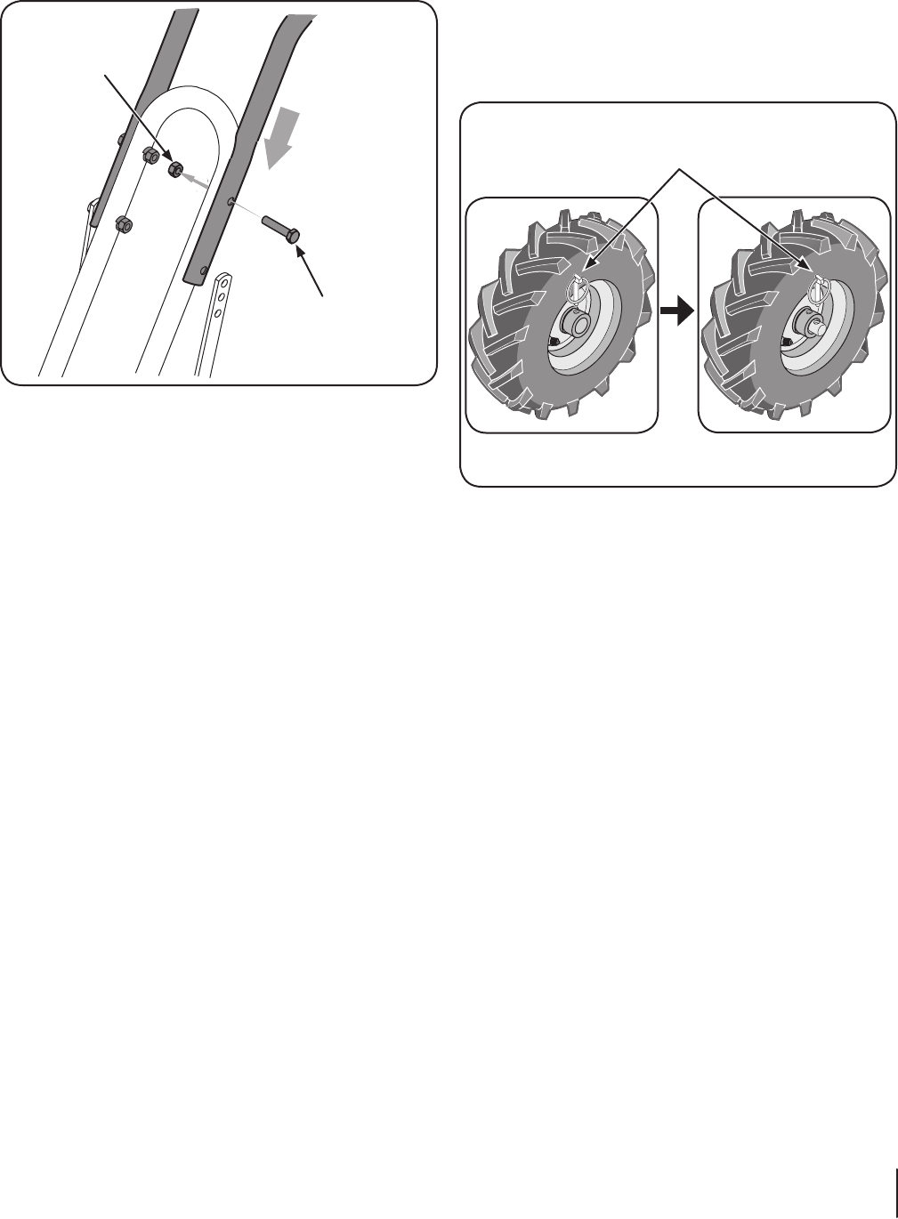
Using two 2. ⁄”-18 x 1-⁄” screws and ⁄”-18 hex nuts, loosely
attach the handlebar support using the upper holes.
Tighten the two screws securely. See Fig. 3-2.
There are three height adjustment holes in the two handlebar 3.
support brackets. Use a setting that will position the
handlebars at approximately waist level when the tines are
3-4” into the soil. Loosely attach the support brackets to
the outside of the handlebar assembly using two ⁄”-18 x
1-⁄” screws and ⁄”-18 hex nuts. Refer to Fig. 3-2.
NOTE: If a support bracket will not move, loosen attaching
screw and nut.
NOTE: The support brackets must be assembled to the
outside of the handlebar assembly.
Tighten all the handlebar mounting hardware securely.4.
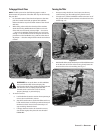
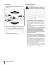
Move Tiller Off Crate
To roll the tiller off the shipping platform, put the wheels in
freewheel, as follows:
Place a sturdy block under the transmission to raise one 1.
wheel about 1” off the ground.
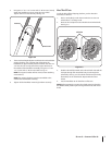
Remove the click pin from the wheel hub and wheel shaft. 2.
See Fig. 3-3.
Slide the wheel fully inward on the wheel shaft . Reinstall the 3.
click pin through the wheel shaft only (not through the
wheel hub). See Fig. 3-3. The wheel should now spin freely
(freewheel) on the wheel shaft. Repeat with the other
wheel.
Use the handlebar to roll the tiller to a flat area.4.
NOTE: Before starting the engine, the wheels must be placed in
the WHEEL DRIVE position (pins through wheel hubs and wheel
shaft).
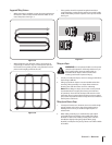
Hex Screw
Hex nut
Figure 3-2
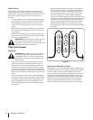
Click Pin
Figure 3-3
7se c t i O n 2 — as s e M b l y & se t -up