


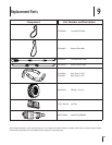
Belt Replacement
If the drive belt needs to be replaced, see your local authorized
dealer or refer to the Replacement Parts Section for ordering
information. Use only a factory-authorized belt as an “over- the-
counter” belt may not perform satisfactorily. The procedure
requires average mechanical ability and commonly available
tools.
Tines
The bolo tines will wear with use and should be inspected
at the beginning of each tilling season and after every 30
operating hours. The tines can be replaced either individually
or as a complete set. See the Replacement Parts Section for tine
identification and part numbers.
Tine Inspection
With use, the tines will become shorter, narrower and pointed.
Badly worn tines will result in a loss of tilling depth, and reduced
effectiveness when chopping up and turning under organic
matter.
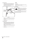
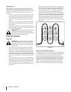
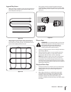
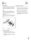
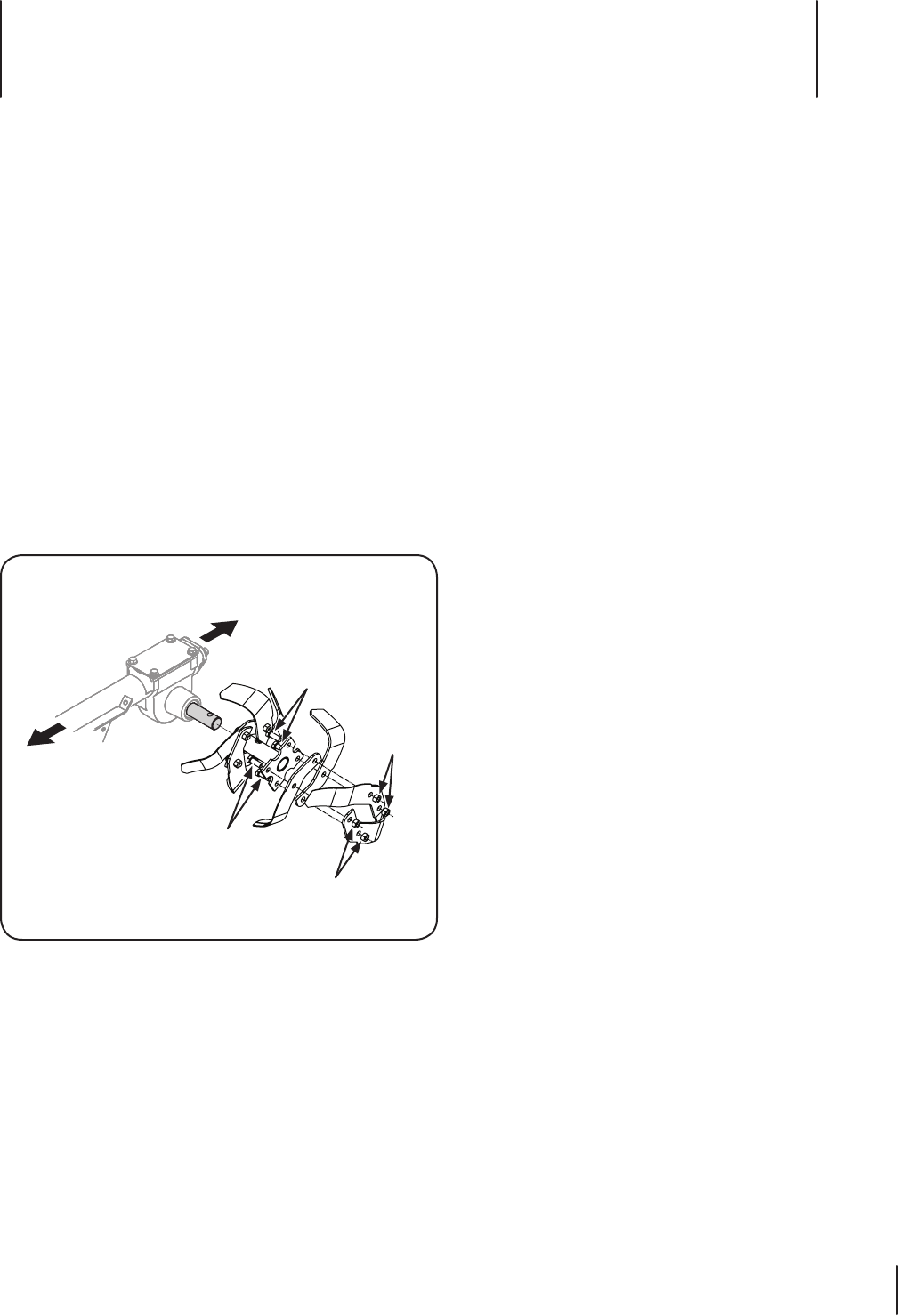
Refer to Fig. 7-1 for the following steps procedures.
Removing/Installing a Single Tine
With the engine shut off and the spark plug wire 1.
disconnected, remove the two screws and nuts that attach
a single tine to a tine holder. If needed, use penetrating oil
on the nuts.
When installing a single tine, be sure to position it so that 2.
its cutting edge (sharp) will enter the soil first as the tiller
moves forward.
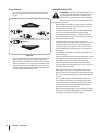
Removing/Installing a Tine Assembly:
A tine assembly consists of eight tines mounted on a tine 1.
holder.
If removing both tine assemblies, mark them “left” and 2.
“right” before removal. Remove the screw and locknut that
secure the tine assembly to the tine shaft. If necessary, use
a rubber mallet to tap the tine assembly outward off the
shaft.
Before reinstalling the tine assembly, inspect the tine 3.
shaft for rust, rough spots or burrs. Lightly file or sand, as
needed. Apply a thin coat of grease to the shaft.
Install each tine assembly so that the cutting (sharp) edge 4.
of the tines will enter the soil first when the tiller moves
forward. Secure the tine assembly to the tine shaft using
the screw and locknut.
Nuts
Screw
Nuts
Screw
Front/Forward
Rear/Operator
Figure 7-1
Service
7
17