


SECTION3: FEATURESANDCONTROLS
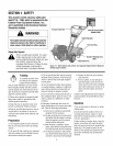
_ ARNING: Before
operatingyour machine,
carefully readand understand
all safety,controls and
operatinginstructions in this
Manual,the separateEngine
Owner's Manual,and on the
decalson the machine.
Failureto follow these
instructions can result in
serious personalinjury.
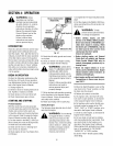
INTRODUCTION
This Section describesthe location and
function ofthe controls on yourtiller. Refer
to the following Section, Operationfor de-
tailed operatinginstructions.
Practice usingthese controls, with the en-
gine shut off, until you understandthe op-
eration ofthe controls and feelconfident
with eachof them.
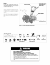
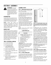
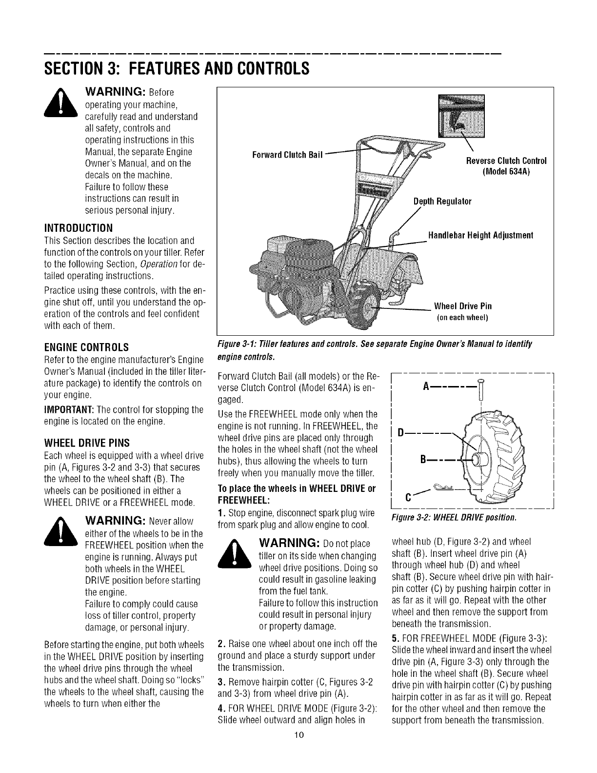
ForwardClutch
Bail ReverseClutchControl
(Model 634A)
gulator
HandlebarHeight Adjustment
Wheel Drive Pin
(oneachwheel)
ENGINE CONTROLS
Referto the enginemanufacturer's Engine
Owner'sManual(included in the tiller liter-
aturepackage)to identify the controls on
your engine.
IMPORTANT:Thecontrol for stopping the
engine is located onthe engine.
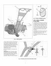
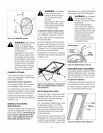
WHEEL DRIVE PINS
Eachwheelis equippedwith a wheeldrive
pin (A, Figures3-2 and 3-3) that secures
the wheelto the wheelshaft (B). The
wheelscan be positioned in either a
WHEELDRIVEor a FREEWHEELmode.
_ WARNING: Neverallow
either ofthe wheelsto bein the
FREEWHEELposition whenthe
engineis running. Alwaysput
both wheelsin theWHEEL
DRIVEposition before starting
the engine.
Failureto comply could cause
loss of tiller control, property
damage,or personalinjury.
Beforestartingthe engine,put bothwheels
in the WHEELDRIVEposition by inserting
the wheel drive pins through the wheel
hubsandthewheelshaft. Doingso "locks"
the wheels to the wheelshaft, causing the
wheelsto turn when eitherthe
Figure3-1: Tiller features and controls.See separateEngineOwner's Manual to identify
enginecontrols.
Forward ClutchBail (all models) or the Re-
verse ClutchControl (Model 634A) is en-
gaged.
Usethe FREEWHEELmode only whenthe
engineis not running, in FREEWHEEL,the
wheeldrive pins are placedonly through
the holes in thewheelshaft (notthe wheel
hubs), thus allowing the wheels to turn
freely whenyou manually movethe tiller.
Toplacethewheels in WHEELDRIVEor
FREEWHEEL:
1. Stopengine,disconnectsparkplug wire
from sparkplug andallowengineto cool.
_ WARNING: Donotplace
tiller on its sidewhen changing
wheeldrive positions. Doingso
could result in gasolineleaking
from the fuel tank.
Failureto follow this instruction
could result in personal injury
or property damage.
2. Raiseone wheelabout one inch off the
ground and placeasturdy support under
the transmission.
3. Removehairpin cotter (C,Figures3-2
and 3-3) from wheel drive pin (A).
4. FORWHEELDRIVEMODE(Figure3-2):
Slide wheeloutward and align holes in
Figure3-2: WHEELDRIVEposition.
wheelhub (D, Figure3-2) and wheel
shaft (B). Insertwheel drive pin (A)
through wheel hub (D)and wheel
shaft (B). Securewheeldrive pin with hair-
pin cotter (C) by pushing hairpin cotter in
asfar as it will go. Repeatwith the other
wheeland then removethe support from
beneaththe transmission.
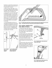
5. FORFREEWHEELMODE(Figure3-3):
Slidethewheelinwardandinsertthe wheel
drive pin (A, Figure3-3) onlythrough the
hole in the wheel shaft (B). Securewheel
drivepin with hairpincotter (C)by pushing
hairpin cotter in asfar asit will go. Repeat
for the other wheeland then removethe
support from beneaththetransmission.
lO