


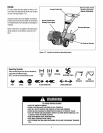

SECTION2: ASSEMBLY
WARNING: To prevent
personalinjury or property
damage,do notstarttheengine
until all assemblysteps are
completeandyou haveread
and understandthe safety and
operatinginstructions in this
manual.
INTRODUCTION
Carefullyfollow these assemblysteps to
correctly prepareyour tiller for use. It is
recommendedthat you readthis Section
in its entirety beforebeginning assembly.
NOTE: Various tiller models are
ASSEMBLYSTEPS
STEP 1: UNPACKINGINSTRUCTIONS
NOTE:While unpacking, do not severely
bendany control cables.
1.Thetiller weighs approximately133 lbs.
Donot attempt to remove it from the ship-
ping platform until instructed to do so m
these Assembly steps.
2. Removeanypackaging materialfrom
the carton. Removeany staplesfrom the
bottom ofthe carton and removethe car-
ton from the shipping platform.
3. Removeallunassembledpartsand the
separatehardwarebagfrom the carton.
presented in this Manual Use only the Checkthat you havethe items listed in the
information appropriate for your tiller LooseParts List (contactyour localdealer
model Engine styles vary by model Your or the factory itemsare missing or dam-
engine may appear differently than those aged).
illustratedin this manual.
INSPECTUNIT
Inspectthe unitand carton for damageLm-
mediatelyafter delivery. Contactthe cam-
er (trucking company) if you find or
suspectdamage. Inform them of thedam-
1
ageand request instructions for filing a 1
claim. Toprotect your rights, put your
claim inwriting and ma_la copyto the car- 1
rier within 15 days after the unit hasbeen 1
delive'ed. Contact Troy-Bilt LLCil you 6
needassistancein this matter. 2
2
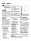
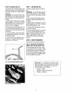
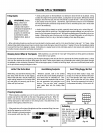
TOOLSMATERIALSNEEDED
NOTE: Use the screw length template
(Fig.2-1) toidentify screws
LoosePartsList
Qty. Description
HandlebarSupport (seeA, Fig. 2-2_
HandlebarAssembly(seeK,Fig.2-2)
Hardwarebag contents:
Slotted hd. screw #10-24 x 2'
Hex hd.screw 1/4-20 x 1-1 '4
Hex hd.screw 5/16-18 x 1-1 2"
Hex hd.screw. 3/8-16 x 3/4
FlatWasher.3/8
6 Split Iockwashe_5/16"
m
Figure2-1:Toidentifylengthofscrews,place
screwontemplateasshownandmeasuredis-
tancebetweenbottomofscrewheadandtipof
scrBw,
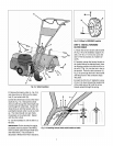
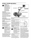
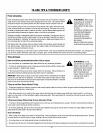
STEP 2: ATTACH HANDLEBAR
1. Looselyattachthe legsofthe handlebar
support (A, Fig.2-2) to the inner sides of
thetiller frame usingtwo 3/8"-16x 3/4"hex
hd. screws (B), 3/8"flat washers(C), 3/8"
lock washers (GG_,and 3/8"-16 hexlock-
nuts (D_,
2. Therearethree heightadjustment holes
in the two handlebarsupport brackets(.E
and E Fig. 2-2). Usea setting that will po-
sition the handlebarsat approximately
waist levelwhenthetines are3"-4"intothe
so_l. Looselyattachthe support brackets
to the handlebarsupport (.A_using two
1 Hex Iocknut. 1/4"-20 5Pi6"-18x 1-1/2" screws (G).5/16" split
Ill 3,8" open-endwrench* 6 Hex nut. 5/16"-18 Iockwashers(.H)and5/16"-18 hexnuts(I).
(.2) 7/16'open-end wrench" 1 Hex nut #10-24 NOTE: If a support bracketwill not move
12_ 1/2" open-end wrench* 2 Hex Iocknut.3,8"-16 loosenattaching screw (J) and nut.
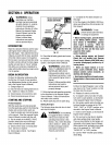
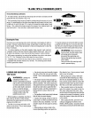
(2) 946" open-end wrench* 1 Spring, cable(seeW, Fig.2-5_ 3. Attach the handlebarassembly (.K_to
1 Bracket.forward clutchcable the handlebarsupport (A) usingfour 5.
(1) Largead Jstablewrench (.seeP,Fig.2-4_ 16"-18x 1-1/2" screws (.G_,5/16" split
_Models634F/634Bonly} 2 Lockwasher 3/8
(.1J Scissors to trim plasticties/
(1) Ruler (for belttension check_
111 Block of wood (to support tiller when
remowng wheels)
111 Tire pressure gauge(for modelswith
pneumatictires_
Ill Cleanoil funnel
111 Motor oil Refertothe Engine0wner's
Manualfor oil specificationsand
quantityrequired.
* Adjustablewrenches may Deused,
2
1 *Bracket reverseclutch cable
*Model 634F& 634B only
IMPORTANT:Motor oil must beaddedto
the enginecrankcase beforetheengine is
started. Followthe instructions inthis
Sectionand in theseparateEngine
Owner'sManual.
*Self-tappingscrew. 1/4-20 x 1/2" IockwashersIHI and5/16"-18 hexnuts (I).
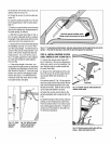
Tightenthe four screws securely
4. Tighten all handlebar mounting hard-
waresecurely.
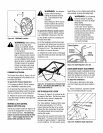
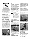
STEP3: MOVE TILLER OFF
Toroll thetiller off the shipping platform.
put the wheels in freewhee asfollows:
1. Placea sturdy block underthetransmis-
NOTE: LEFTandRIGHTsidesofthetiller sion to raise one wheelabout l" off the
are as viewedfrom the operator's position ground.
behind thehandlebars.