


11Section 5 — operation
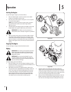
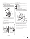
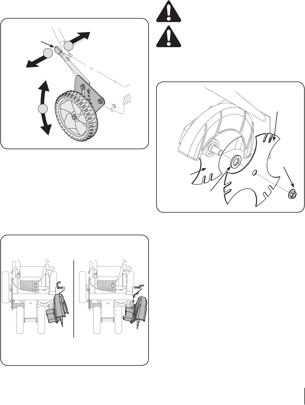
Edging Along a Curb
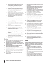
The right, rear wheel of the edger can be lowered into one of five
positions to ease the task of edging along a curb. To adjust the
height of curb wheel, proceed as follows:
1. Lower the right, rear wheel by moving the curb height
adjustment lever slightly to the left. See Figure 5-3.
3
2
1
Curb Height
Adjustment
Lever
Figure 5-3
2. Pivot the right, rear wheel into an applicable position in
relation to the height of the curb to be edged along.
3. Release the curb height adjustment lever to lock the wheel
in position. See Figure 5-3.
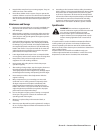
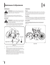
Beveling
In order to achieve a bevelled edge, set the bevel adjustment
lever (refer to the Assembly & Set-Up Section) in the first (left
hand) or third (right hand) notch to place the edger blade in
position for beveling. See Figure 5-4.
Right-Hand Position Left-Hand Position
Figure 5-4
Trenching (If equipped)
You can utilize the edger’s optional trenching feature in order
to create a wider cutting path for such things as laying wire for
landscape lighting.
WARNING! Disconnect the spark plug wire and
ground against the engine before performing the
following steps.
WARNING! The edger blade is sharp. Wear leather
work gloves to protect your hands when working
around the edger blade.
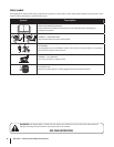
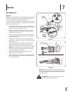
1. Use two wrenches (one wrench to prevent the hex bolt
head from spinning and the other to unthread the flange
nut) to remove the flange nut that secures the edger blade,
leaving the edger blade in place. See Figure 5-5.
Flange Nut
Flat Washer
Edger Blade
Tri-Star Blade
Figure 5-5
2. Install the additional edger blade supplied with your
machine and the flat washer. See Figure 5-5.
3. Secure with the flange nut removed earlier. Use a torque
wrench to tighten the flange nut to between 37 foot-lbs.
and 50 foot-lbs.
NOTE: Make certain that the drive belt is seated correctly
on the blade spindle and that it is riding smoothly on the
spindle sheaves and is not pinched between them. Repeat
the first three steps if belt is pinched.