


14 Section 5: Maintenance
Before inspecting, cleaning or servicing the machine, shut off engine, wait for all moving parts to
come to a complete stop, disconnect spark plug wire and move wire away from spark plug. Remove
ignition key on electric start models.
Failure to follow these instructions can result in serious personal injury or property damage.
WARNING
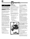
INSPECTING AND REPLACING
THE DRIVE BELT
The drive belt can be inspected or
replaced from beneath the machine deck.
Note that the belt should not require
inspection for many hours of operation.
Belt Inspection
Stop the engine and let all moving parts
stop. Disconnect the spark plug wire and
move it away from the spark plug. Re-
move the ignition key on electric start
models.
1. For convenience, we recommend that
you place the unit on a raised platform for
easier access to the underside of the deck.
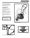
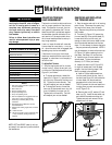
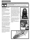
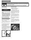
2. Remove the rubber debris flap (A,
Figure 5-3) by removing one of the small
E-rings (B) at the ends of the retainer rod
and then sliding the retainer rod out.
3. Remove the rear belt cover by using a
1/2" wrench to remove the screw (C,
Figure 5-3) in the rear belt cover. Examine
the belt. Feed it around the rear (engine)
pulley so the entire belt can be examined.
If cracks or other damage are noted, a
new belt is needed. Otherwise, clean and
reinstall the belt cover and debris flap.
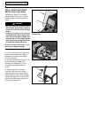
Belt Replacement
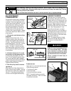
4. Remove the spindle head by taking off
the hex nut (A, Figure 5-4) at the bottom
of the spindle, using a 3/4" socket wrench.
(While loosening the nut, prevent the spin-
dle head from turning by inserting a
screwdriver or rod into hole B, Figure 5-5,
at the top-front of the deck. Be sure to
align one of four holes in the pulley with
the deck hole first.)
5. With a 1/2" wrench, remove the screw
(D, Fig. 5-3) from the front belt cover-
spindle mounting plate. Then remove the
other four screws securing the belt cover-
spindle mounting plate (E, F, G and H, Fig.
5-3). Carefully lower the drive housing
and the belt cover-spindle mounting plate.
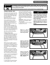
Note precisely how the belt is routed along
the pulleys. (See Figure 5-6.) Slip the belt
off the rear pulley (H, Figure 5-6), then off
the other pulleys. NOTE: The nut on the
idler arm V-pulley must be removed in
order to take off the belt (the screw may
need to be held with an Allen wrench).
Install the new belt along the exact same
path.
6. Clean parts of all debris. Replace the
lower drive shaft housing and front belt
cover-spindle mounting plate, the spindle
head, the wear cup, the rear belt cover,
and the debris flap.
7. Check for correct belt tension. See
“Adjusting Trimmer Head Engagement” in
this Section.
Figure 5-3
Figure 5-4 Figure 5-5
A
B
D
E
F
G
H
C
A
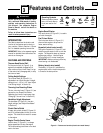
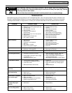
DANGER
KEEP HANDS and FEET AWAY
THROWN OBJECT H
Objects such as rocks, peb
ble
small d
ebris will
be throw
n violen
the
cu
ttin
g head, resulting in signific
hazard to eyes an
d exposed bo
dy parts
Keep c
hildre
n, pets and bystanders 50
fe
et aw
ay from m
achine w
hile operating
.
Be alert t
o h
idden obstacles.
ROTATING CUTTING HEAD
Do not service o
r adj
ust c
utting head or
other moving parts unless engine is stop
ped
and spark p
lu
g wire
is discon
nected.
19
0
44
0
3
(1
/
97)
B
Figure 5-6
H