


19
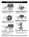
4. Disconnect the spark plug wire.
5. Clean dirt from around the spark plug. Remove the
spark plug from the cylinder head by turning a 5/8 in.
socket counterclockwise.
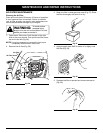
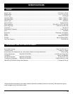
6. Remove the engine cover (Fig. 63).
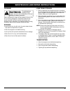
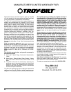
7. Clean dirt from around the rocker arm cover.
Remove the screw holding the rocker arm cover with
a large flat blade screwdriver or Torx T-25 bit
(Fig. 65). Remove the rocker arm cover and gasket.
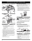
3. Remove the screw behind the engine cover (Fig. 64).
Rocker Arm Cover
Screw
Fig. 64
Fig. 65
Spark Plug Hole
8. Pull the starter rope slowly to bring the piston to the top
of its travel, (known as top dead center). Check that:
• The piston is at the top of its travel while looking in
the spark plug hole (Fig. 65)
• Both rocker arms move freely, and both valves are
closed
If these statements are not true, repeat this step.
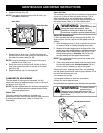
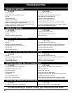
9. Slide the feeler gauge between the rocker arm and
the valve return spring. Measure the clearance
between the valve stem and rocker arm (Fig. 66).
Measure both the intake and exhaust valves.
The recommended clearance for the intake and exhaust
is .003 – .006 in. (.076 – 0.152 mm).
Use a standard automotive feeler gauge at .005 (0.127mm).
The feeler gauge should slide between the rocker arm and
valve stem with a slight amount of resistance, without
binding. Figure 67 shows how to measure the clearance.
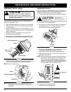
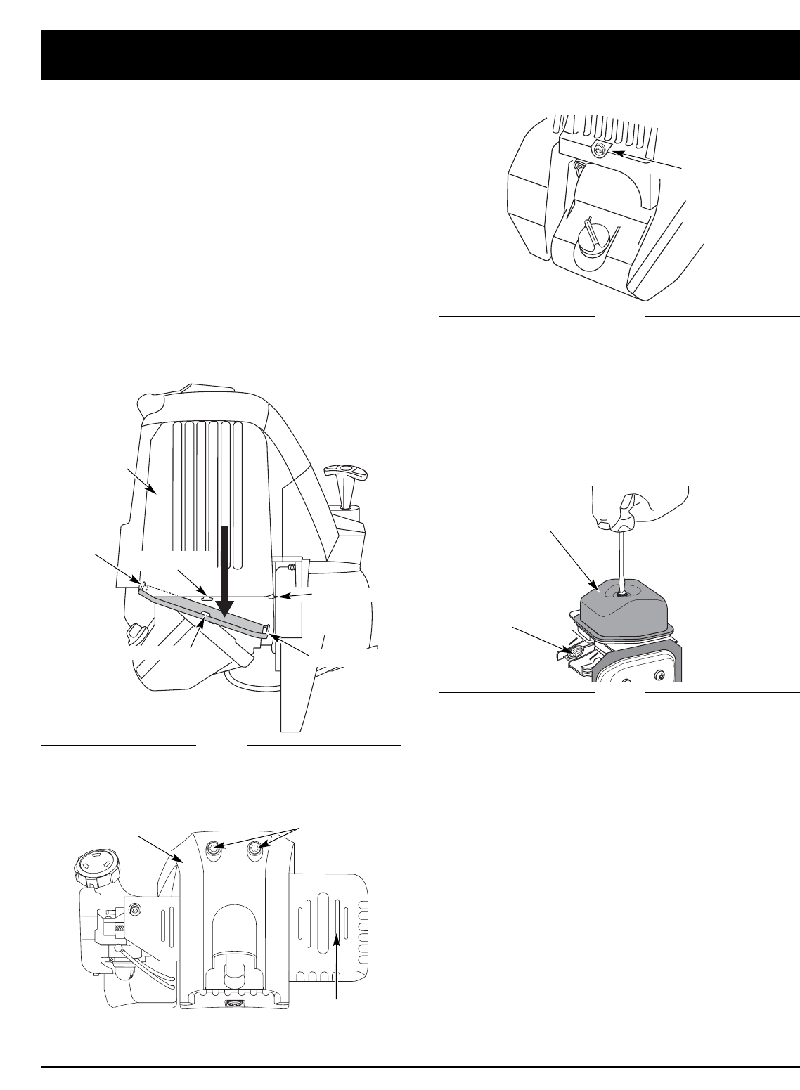
Remove
Screws
Fig. 62
Engine Cover
2. Remove the two (2) screws on top of the engine cover
with a Flat-head or T-25 Torx screwdriver (Fig. 63).
Fig. 63
Engine Cover
Muffler
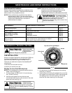
ROCKER ARM CLEARANCE
This requires disassembly of the engine. If you feel
unsure or unqualified to perform this, take the unit to an
authorized service center.
NOTE: Inspect the valve to rocker arm clearance with a
feeler gauge after the first 10 hours of operation
and then every 25 hours of operation thereafter.
• The engine must be cold when checking or adjusting
the valve clearance.
• This task should be performed inside, in a clean,
dust free area.
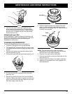
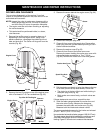
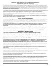
1. Remove the muffler cover by pressing down on it,
separating it from the engine cover. Using a flat
blade screwdriver, disengage the middle and front
tabs and slots first. The cover will hinge off from the
rear tab (Fig. 62).
Top View Of The Engine
Front Slot
Front Tab
Middle Tab
Middle Slot
Rear Slot
and Tab
MAINTENANCE AND REPAIR INSTRUCTIONS