


15
MAINTENANCE AND REPAIR INSTRUCTIONS
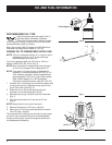
Idle Adjustment Screw
Adjust Idle Speed Screw
If, after checking the fuel and cleaning the air filter, the
engine still will not idle, adjust the idle speed screw as
follows:
1. Start the engine and let it run at a high idle for a minute
to warm up. Refer to Starting/Stopping Instructions.
NOTE: Ensure the tines are not in contact with the
ground when adjusting the idle.
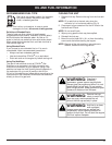
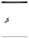
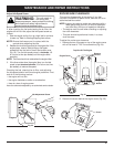
2. Release the throttle trigger and let the engine idle. If the
engine stops, insert a small phillips or flat blade
screwdriver into the hole in the air filter/muffler cover
(Fig. 23). Turn the idle speed screw in, clockwise, 1/8
of a turn at a time (as needed) until the engine idles
smoothly.
NOTE: The tines should not rotate when the engine idles.
3. If the tines rotate when the engine idles, turn the idle
speed screw counterclockwise 1/8 of a turn at a time
(as needed), to reduce idle speed.
Checking the fuel, cleaning the air filter, and adjusting
the idle speed should solve most engine problems. If not
and all of the following are true:
• the engine will not idle
• the engine hesitates or stalls on acceleration
• there is a loss of engine power
Have the carburetor adjusted by an authorized service dealer.
Fig. 23
ROCKER ARM CLEARANCE
This requires disassembly of the engine. If you feel
unsure or unqualified to perform this, take the unit to an
authorized service center.
NOTE: Inspect the valve to rocker arm clearance with a
feeler gauge after the first 10 hours of operation
and then every 25 hours of operation thereafter.
• The engine must be cold when checking or adjusting
the valve clearance.
• This task should be performed inside, in a clean,
dust free area.
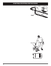
To adjust the rocker arm clearance:
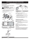
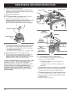
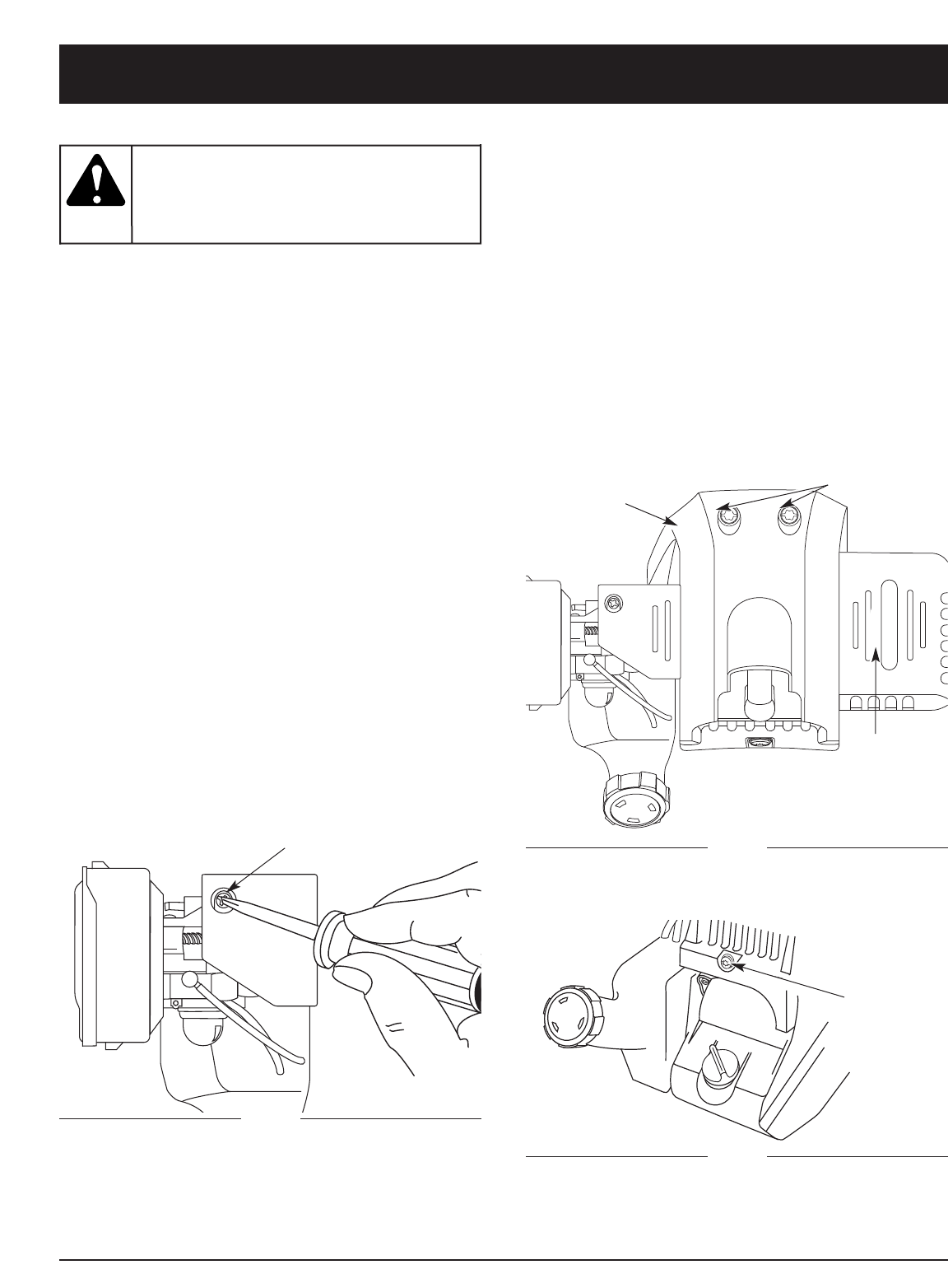
1. Remove the two (2) screws on top of the engine cover
with a Flat-head or T-25 Torx screwdriver (Fig. 24).
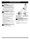
This unit needs to
run during idle
speed adjustment. Wear protective clothing
and observe all safety instructions to
prevent serious personal injury.
WARNING:
Remove
Screws
Engine Cover
Fig. 24
Muffler
Top View Of The Engine
2. Remove the screw behind the engine cover (Fig. 25).
Screw
Fig. 25