


7
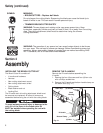
Assembly (continued)
INSTALLING AND ADJUSTING THE J-HANDLE
Installing
1. Remove the screws, nuts, clamp pieces that were
installed on the J-handle for shipping.
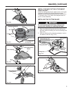
2. Lay the unit on its side. On the bottom of the shaft
housing is a pre-drilled hole. With a Flat Blade or
Torx T-20 Screwdriver, insert the Anti-Rotation
Screw through the hole in the bottom clamp and
into the hole in the shaft housing (Fig. 2-2). Tighten
securely.
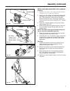
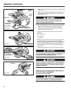
3. Place the J-handle between the top and middle
clamp pieces (Fig. 2-3).
4. While holding the three pieces together, install the
four (4) screws through the top clamp and into
middle clamp.
NOTE: The holes in the top and middle clamp will
line up only when assembled correctly.
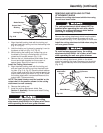
5. Place the clamps and J-handle the over the shaft
housing and onto the bottom clamp.
6. Hold each hex nut in the bottom clamp recess with
a finger. Start screws with a large Phillips screw-
driver. Do not tighten until you make the handle
adjustment.
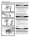
Adjusting
7. Loosen the screws so that the J-handle can be
easily moved in the clamp assembly. Do not
remove the screws or nuts.
8. Slide the J-handle in or out until the arrow/white
line on the decal touches the clamp assembly
(Fig. 2-4).
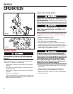
9. While holding the unit in the operating position
(Fig. 2-5), position the J-handle to the location
that provides you the best grip.
10. Tighten the clamp screws evenly, until the J-handle
is secure.
Shaft Housing
Anti-rotation screw
Bottom Clamp
Pre-drilled Hole
Decal
(4) Screws
Top Clamp
J-Handle
Middle Clamp
Bottom Clamp
Fig. 2-3
Fig. 2-2
Fig. 2-4
Fig. 2-5
Nuts