


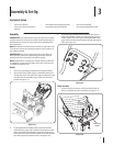
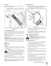
2. Remove lock nuts and screws securing one of the flange
keepers to the chute assembly. Loosen the fasteners of the
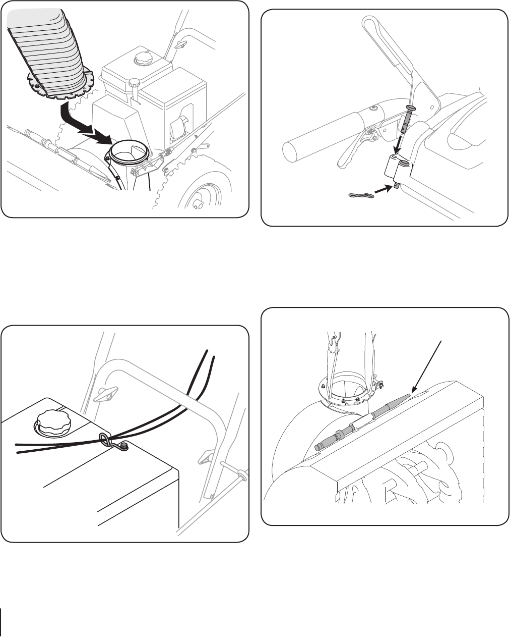
other two flange keepers. See Figure 3-3.
3. Place chute assembly onto chute base as shown in Figure
spiral end of chute directional control, and the two flange
keepers are beneath the flange on the chute base.
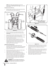
Figure 3-4
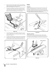
Secure flange keeper removed earlier with lock nuts and
screws. Tighten down nuts securing the other two flange
keepers. See Figure 3-3.
5. Re-tighten the hardware securing the chute crank bracket.
Check that the chute cables are properly routed through
the cable guide on top of engine shroud. See Figure 3-5.
Figure 3-5
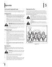
Set-Up
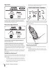
Shear Pins
A pair of replacement auger shear pins and bow tie cotter pins
have been included with your snow thrower. There are holes
provided in the plastic dash panel for convenient storage of the
shear pins. Push the pins through the holes in the dash panel and
Figure 3-6
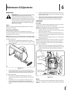
Chute Clean-Out Tool
The chute clean-out tool is fastened to the top of the auger
housing with a mounting clip and a cable tie at the factory. Cut
the cable tie before operating the snow thrower. See Figure 3-7.
Clean-out Tool
Figure 3-7
8 Section 3— ASSembly & Set-Up