


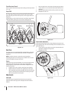


NOTE: Make sure to remove the piece of wood blocking the
impeller.
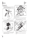
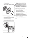
Check the auger drive belt adjustment. With the auger clutch
lever in the disengaged position, the top surface of the new belt
should be even with the outside diameter of the pulley.
To adjust, disconnect ferrule from brake bracket assembly.
Thread ferrule in (towards idler) to increase tension on belt, or
out to decrease belt tension.
NOTE: The brake puck must always be firmly seated in the pulley
groove when auger control is disengaged.
CAUTION:
from the Assembly & Set-up section before operating
the snow thrower.
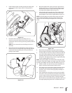
Drive Belt Replacement
If not already done, remove the auger drive belt from the
Use a wrench to rotate the idler pulley away from the backside
of the drive belt to relieve the tension and slip the drive belt
off the idler pulley. Carefully release the idler pulley. See
Figure 7-8.
2
3
1a
1b
Figure 7-28
2. Roll the drive belt off the lower drive pulley and then remove
the belt from the engine pulley.
3. Install the new belt on the engine pulley, then seat around the
lower drive pulley and re-tension with the idler pulley.
Reassemble by performing the previous steps in the
opposite order and manner of removal.
Changing Friction Wheel
The rubber on the friction wheel is subject to wear and should
be checked after the first 25 hours of operation, and periodically
thereafter. Replace the friction wheel if any signs of wear or
cracking are found.
Drain the gasoline from the snow thrower.
2. Tip the snow thrower up and forward, so that it rests on the
housing.
3. Remove screws from the frame cover underneath the snow
the axle.
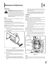
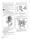
Figure 7-29
hex screw and belleville washer and bearing from left side
Friction Wheel Assembly
Hex Shaft
Remove Hex Screw &
Belleville Washer
Slide Hex
Shaft Out
Right Side
Figure 7-30
5. Holding the friction wheel assembly, slide the hex shaft out
of the right side of the frame. The spacer on the left side
of the hex shaft will fall and the sprocket should remain
hanging lose in the chain.
20 Section 7— Service