


6R
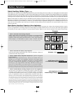
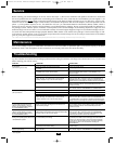
Select Battery Type—REQUIRED
(All models)
CAUTION: The Battery Type DIP Switch setting must
match the type of batteries you connect, or your batteries
may be degraded or damaged over an extended period of
time. See “Battery Selection,” p. 10 for more information.
Battery Type Switch Position
Gel Cell (Sealed) Battery Up
Wet Cell (Vented) Battery Down (factory setting)
Select High AC Input Voltage Point
for Switching to Battery—OPTIONAL*
(All Models)
Voltage Switch Position
145V Up
135V Down (factory setting)
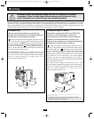
Configuration
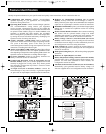
Set Configuration DIP Switches
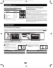
Using a small tool, set the Configuration DIP Switches (located on the front panel, see diagram) to optimize Inverter/Charger operation
depending on your application. RV612UL and RV612ULH models include one set of four DIP Switches. All other models include an additional set
of four DIP switches to configure additional operational functions. Refer to the appropriate section to review the instructions for your spe-
cific model.
A1A2A3A4
A1A2A3A4
INPUT C/B 10A
OUTPUT C/B 12A
B4 B3 B2 B1
A4 A3 A2 A1
Group B Dip Switches (Not on 612 Models)
Group A Dip Switches (All Models)
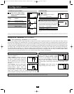
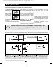
Group A DIP Switches (All Models)
Using a small tool, configure your Inverter/Charger by setting the four Group A DIP Switches (located on the front panel of your unit; see
diagram) as follows:
A1
A2
Operation
(continued)
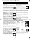
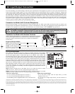
LED Function with Switch in "CHARGE ONLY" Position
Approximate Charge Rate Indication
LEDs
Illuminated Charge Rate
All three lights on Overcharge
error*
Red 75% - 100%
Red & Yellow 50% - 75%
Yellow 25% - 50%
Green 0% - 25%
All three lights off 0%
* If all three lights remain on, an internal fault may exist. Turn off and disconnect the unit.
Then, call Tripp Lite at (773) 869-1234 for assistance.
Resetting Your Inverter/Charger to
Restore AC Power
Your Inverter/Charger may cease supplying AC power or DC charg-
ing power in order to protect itself from overload or to protect your
electrical system. To restore normal functioning:
Overload Reset: Switch operating mode switch to “OFF” and
remove some of the connected electrical load (ie: turn off some of
the AC devices drawing power which may have caused the overload
of the unit). Wait one minute, then switch operating mode switch
back to either “AUTO/REMOTE” or “CHARGE ONLY.”
Output Circuit Breaker Reset: Alternatively, check output circuit
breaker(s) on the unit's front panel. If tripped, remove some of the elec-
trical load, then wait one minute to allow components to cool before
resetting the circuit breaker. See Troubleshooting for other possible
reasons AC output may be absent.
1
2 3
4
5
6
1
2
3
4
5
6
* Most of your connected appliances and equipment will perform adequately when your Inverter/Charger’s High AC Input Voltage Point (DIPSwitch #2 of Group A) is set to 135V and its Low AC Voltage Input Point (DIPSwitches #3 and #4 of Group A or DIPSwitch #3 for
612 models) are set to 95V. However, if the unit frequently switches to battery power due to momentary high/low line voltage swings that would have little effect on equipment operation, you may wish to adjust these settings. By increasing the High AC Voltage Point and/or
decreasing the Low AC Voltage Point, you will reduce the number of times your unit switches to battery due to voltage swings.
200502023 RV Series Inverter-Charger Owner’s Manual.qxd 3/7/2005 7:42 PM Page 6