


10R
Mounting
WARNING! Mount your Inverter/Charger BEFORE DC battery and AC power
connection. Failure to follow these instructions may lead to personal injury
and/or damage to the Inverter/Charger and connected systems.
Tripp Lite manufactures a variety of different Inverter/Chargers with a variety of different mounting options for use in vehicular or non-vehicular
applications. Tripp Lite recommends permanent mounting of your Inverter/Charger in any of the configurations illustrated below. User must
supply mounting hardware and is responsible for determining if the hardware and mounting surface are suitable to support the weight of the
Inverter/Charger. Contact Tripp Lite if you require further assistance in mounting your Inverter/Charger.
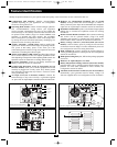
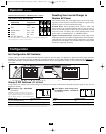
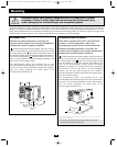
612 Models Only
Whether mounted horizontally or vertically, the
Inverter must be located in an enclosed compartment,
shielded from outside weather conditions.
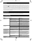
Using the measurements from the diagram, install two user-sup-
plied ¼" (6 mm) fasteners into a rigid horizontal surface, leaving
the heads slightly raised. Slide the Inverter/Charger back over
the fasteners to engage the mounting slots molded on the bottom of
the Inverter/Charger cabinet. Install and tighten two user-sup-
plied ¼" (6 mm) fasteners into the mounting feet molded on the
front of the Inverter/Charger cabinet.
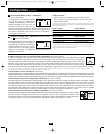
The polycarbonate cabinet and mounting feet of your
Inverter/Charger are durable enough to allow for vertical mount-
ing as well, if your vehicle compartment requires this configura-
tion. For vertical mounting, the control panel of the
Inverter/Charger should face up.
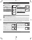
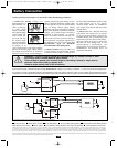
All Models Except 612 Models
Note: When operating RV1012UL and RV2012UL
models in a marine application, refer to the
accompanying marine owners' manual addendum.
Whether mounted horizontally or vertically, the
Inverter must be located in an enclosed compartment,
shielded from outside weather conditions.
Using the measurements from the diagram, install two user-sup-
plied ¼" (6 mm) fasteners into a rigid horizontal surface, leaving
the heads slightly raised. Slide the Inverter/Charger forward
over the fasteners to engage the mounting feet molded on the
front of the Inverter/Charger cabinet. Install and tighten
additional user-supplied ¼" (6 mm) fasteners into the mounting
feet molded on the rear and sides of the Inverter/Charger
cabinet*. The rear feet extend beyond the unit’s cabinet to
provide for adequate ventilation space behind the cooling fan(s);
they should not be removed.
The polycarbonate cabinet and mounting feet of your
Inverter/Charger are durable enough to allow for vertical mount-
ing as well, if your vehicle compartment requires this configura-
tion. For vertical mounting, the control panel of the
Inverter/Charger should face up.
5.87 in.
(14.91 cm.)
1.64 in.
(4.15 cm.)
5.87 in.
(14.91 cm.
)
5.57 in.
(14.16 cm.)
5.57 in.
(14.16 cm.)
9.59 in.
(24.35 cm.)
9.59 in.
(24.35 cm.)
6.75 in.
(17.1 cm)
7.87 in.
(20 cm)
6.75 in.
(17.1 cm)
4.5 in.
(11.4 cm)
A
C
B
▼
A
B
▼
A
B
C
A
B
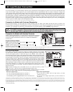
Note: RV model cabinets may have different front panel features, but all mount as per the figure above, or via the Lateral
Mounting Bracket, illustrated at left.
* All models include front and rear mounting feet. Select
models include side mounting feet.
200502023 RV Series Inverter-Charger Owner’s Manual.qxd 3/7/2005 7:42 PM Page 10