


5
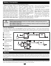
Vehicular Applications
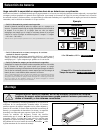
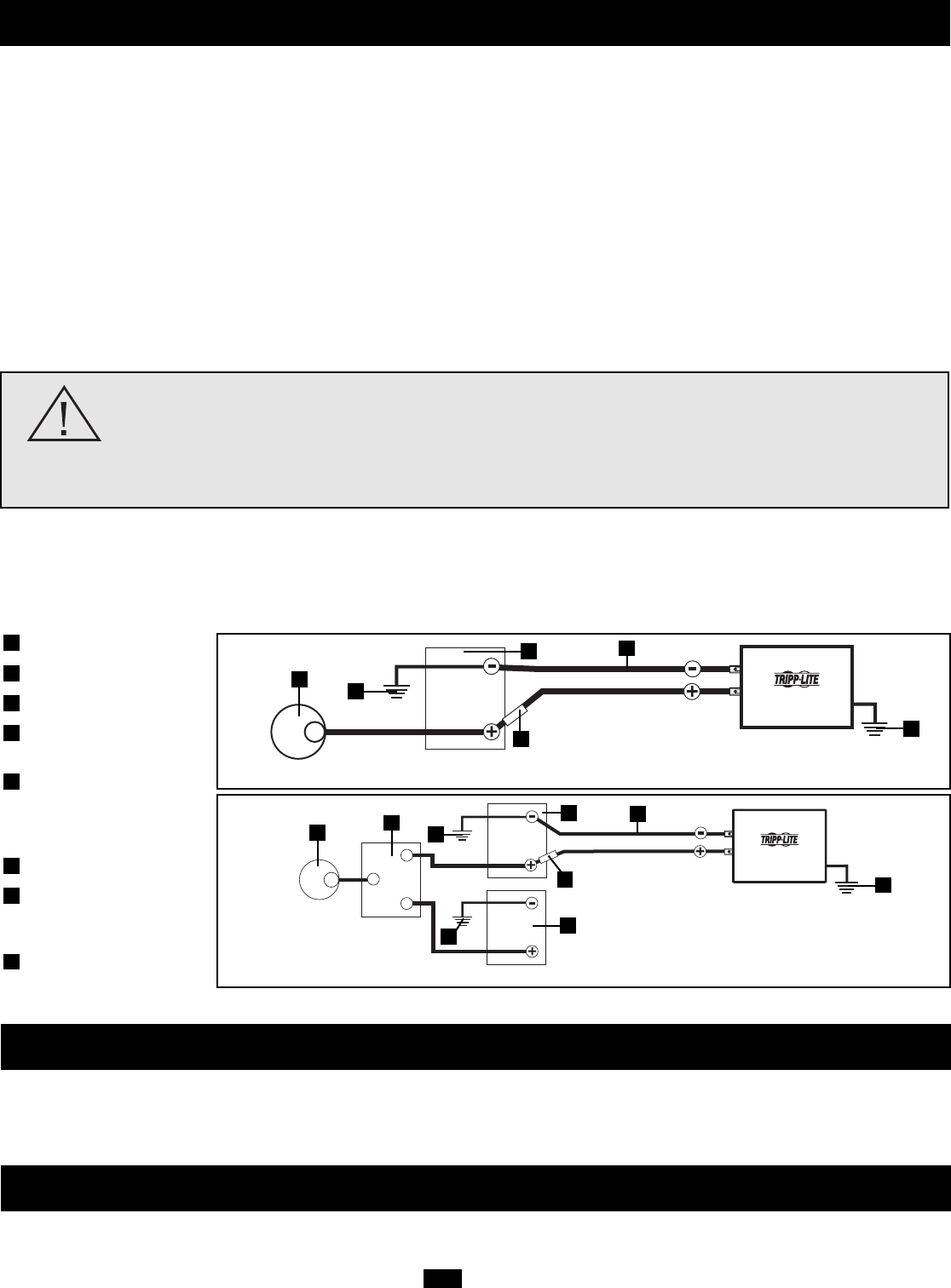
Your Inverter’s Nominal DC Input Voltage must match the voltage of your battery or batteries—12 Volts in most vehicular applications.
It is possible to connect your Inverter to the main battery within your vehicle’s electrical system. In many vehicular contexts, the Inverter
will be connected to one or more dedicated auxiliary (house) batteries which are isolated from the drive system to prevent possible draining
of the main battery.
Battery Connection
• Connect DC Wiring: Though your
Inverter is a high-efficiency converter of
electricity, its rated output capacity is
limited by the length and gauge of the
cabling running from the battery to the unit.
Use the shortest length and largest diameter
cabling (maximum 4 AWG or 5 mm) to fit
your Inverter’s DC Input terminals. Shorter
and heavier gauge cabling reduces DC
voltage drop and allows for maximum
transfer of current. Your Inverter is capable
of delivering peak wattage at up to 200% of
its rated continuous wattage output for brief
periods of time. Heavier gauge cabling
should be used when continuously operating
heavy draw equipment under these
conditions. Tighten your Inverter and
battery terminals to approximately 3.5
Newton-meters of torque to create an
efficient connection and to prevent
excessive heating at this connection.
Insufficient tightening of the terminals could
void your warranty. See Specifications for
Recommended Cable Sizing.
• Connect Ground: Using a 12-18 AWG
(1-2 mm) wire, directly connect the Main
Ground Screw to the vehicle’s chassis or
earth ground. See the Feature Identification
section to locate the Main Ground Screw.
All installations must comply with national
and local codes and ordinances.
• Connect Fuse: Tripp Lite recommends
that you connect your Inverter’s positive DC
Terminal directly to a fuse(s) and fuse
block(s) within 45 cm (18 inches) of the
battery. The fuse’s rating must equal or
exceed the Minimum DC Fuse Rating listed
in your Inverter’s specifications. See
Specifications for fuse recommendations.
See diagrams below for proper fuse
placement.
Connect your Inverter to your batteries using the following procedures:
WARNING!
• Failure to properly ground your Inverter to a vehicle’s chassis or earth ground may result in a
lethal electrical shock hazard.
• Never attempt to operate your Inverter by connecting it directly to output from an alternator rather
than a battery or battery bank.
• Observe proper polarity with all DC connections.
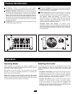
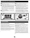
12 Volt Alternator
Vehicle Battery Ground
12 Volt Main Battery
12 Volt Auxiliary (House)
Battery
UL or CE Approved Fuses &
Fuse Blocks (mounted within
18 inches [45 cm] of the
battery)
Battery Isolator
Large Diameter Cabling,
Maximum 4 AWG or 5 mm
to Fit Terminals
12-18 AWG (1-2 mm) Ground
Wire to Vehicle Frame or
Earth Ground
8
7
6
5
4
3
2
1
12 Volt Inverter
12 Volts
12 Volts
12 Volt Main Battery Connection—two DC terminals
12 Volt Inverter
12 Volts
12 Volts
12 Volts
12 Volt Main and Auxiliary (House) Battery Connection (Isolated Parallel)—two DC terminals
1
2
3
5
7
8
8
7
4
5
3
2
2
1
6
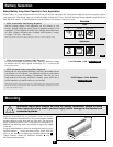
Service
Maintenance
If you are returning your Inverter to Tripp Lite, please pack it carefully, using the ORIGINAL PACKING MATERIAL that came with the
unit. Enclose a letter describing the symptoms of the problem. If the Inverter is within the warranty period, enclose a copy of your sales
receipt. To obtain service you must obtain a Returned Material Authorization (RMA) number from Tripp Lite or an authorized Tripp Lite
service center.
Your Inverter requires no maintenance and contains no user-serviceable or replaceable parts, but should be kept dry at all times. Periodically
check, clean and tighten all cable connections as necessary, both at the unit and at the battery.