20 UH-SVX01A-EN
Installation
Installation: S Type
Unit Mounting
ƽWARNING
Heavy Objects!
Ensure that all hardware used in the
suspension of each unit heater is
more than adequate for the job.
Failure to do so may result in
extensive property damage, severe
personal injury or death.
ƽWARNING
Structural Integrity!
Make certain that the structure to
which the heater is mounted is
capable of supporting its weight.
Under no circumstances must the
gas lines, the venting system, or the
electrical conduit be used to support
the heater; or should any other
objects (i.e. ladder, person) lean
against the heater gas lines, venting
system, electrical conduit for
support. Failure to heed these
warnings may result in property
damage, personal injury, or death.
ƽCAUTION
Lifting/Suspension Methods!
Make certain that the lifting methods
used to lift the heater and the
method of suspension used in the
field installation of the heater are
capable of uniformly supporting the
weight of the heater at all times.
Failure to heed this warning may
result in property damage or
personal injury!
CAUTION
Performance Failure!
Unit heaters must be hung level from
side to side and from front to back.
Failure to do so will result in poor
performance and or premature failure
of the unit.
Install unit heaters to meet
Occupational Safety and Health Act
(OSHA) and CSA requirements. Unit
heaters mounted lower than 8 feet
(2.4m) from the floor must be
equipped with an OSHA fan guard.
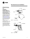
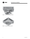
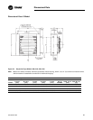
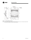
Note: Units equipped with the
motor mounted to the fan
guard require two point
suspension. Units equipped
with a shelf mounted motor
are required to be suspended
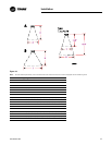
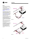
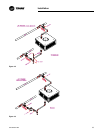
at four points. Refer to
Figure 20 and Figure 21 for
two point suspension and
refer to Figure 9 for four point
suspension.
Nutserts are provided at the top of all
units for suspension purposes.
Support rods should support the total
unit weight to assure that no strain is
placed on supply and return piping.
Provisions for removal of the unit
from the suspension rods may be
desirable for servicing purposes.
Units must hang level vertically and
horizontally.
Provide sufficient clearance around
units for maintenance purposes.
Isolators are not required but may be
desirable for some applications.
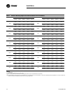
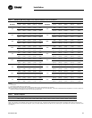
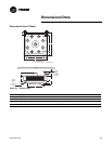
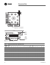
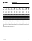
Refer to “Dimensional Data.”
Piping
To provide proper coil operation,
follow all piping recommendations
listed in this manual.
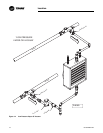
See Figure 13 through Figure 17 for
proper pipe connections.
Follow standard practices and codes
when installing the piping. Provide
swing joints for expansion purposes,
unions and shut-off valves for
servicing purposes and as illustrated
in Figure 13 through Figure 17,
valves and traps for control
purposes. Use 45 degree angle run-
offs from all supply and return mains.
Dirt pockets should be the same pipe
size as the return tapping of the unit
heater. Also, pipe size in the
branchoff should be the same size as
the tapping in the traps. Beyond the
trap, the return lateral pipe should be
increased one size up to the return
main.
It is assumed that the design
engineer has selected the type of
system to be used. The sketches
shown are for different types of
steam systems or hot water systems.
For sizing of piping, traps, filter, etc.,
consult ASHRAE guides of the
manufacturer’s literature on these
products.
It is important that the system be
kept clean. Care should be exercised
that excessive joint materials or
foreign substances be kept out of the
system.
On steam systems it is
recommended that the unit be
installed level for proper condensate
drainage. Swing joints should be
used in piping, and pipes should be
pitched down from units so that
condensate can drain freely.


