


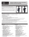

Servicing Sprinkler Mechanism
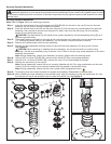
WARNING! Never stand or lean over the sprinkler while the irrigation system is being filled, during manual or
automatic operation or when performing sprinkler service procedures. Direct contact with irrigation spray, a failed
or improperly installed sprinkler connection or sprinkler components forcibly ejected upward under pressure can cause
serious injury.
Servicing Sprinkler Mechanism
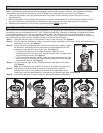
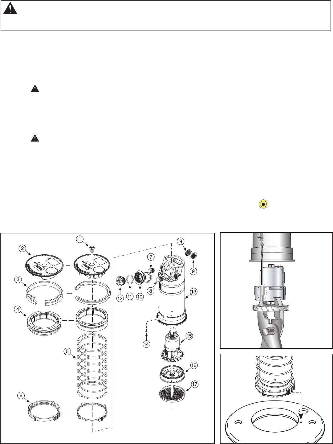
Note: Refer to Figure 12 for the following procedure.
Step 1 – Insert the hooked end of the multi-purpose tool (P/N 995-83) into the slot in the cap (2) and pull the riser
assembly up until there is enough clearance to handle.
Step 2 – Insert the hooked end of the tool into the snap ring slot (3). Pull the snap ring inward towards the sprinkler
assembly, then upward to remove from the groove in body. Hold onto the riser body (13) and carefully
extract it from the sprinkler body.
CAUTION: The seal/retainer (4) will rapidly move upward (caused by the decompressing spring [5]) as it
clears the sprinkler body.
Step 3 – Three small tabs are provided on the edge of the multi-purpose tool. Insert tabs into the debris filter screen
(17). Holding the plastic base of riser assembly, turn the screen counterclockwise to remove.
Step 4 – Remove the variable stator (16) from riser assembly.
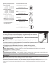
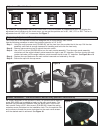
Step 5 – Remove the drive assembly retaining screw (14) and pull the drive assembly (15) using a pair of pliers.
See Figure 13.
CAUTION: When removing or installing the drive assembly, do not use the turbine to pull the drive
assembly. Use the drive assembly body to extract it out. Failure to comply may cause separation of the drive
assembly components.
Note: During reassembly, ensure drive assembly is properly aligned with the retaining screw.
Step 6 – Using a 5/8" nut driver (P/N 995-99), unscrew main nozzle (12) from nozzle base assembly.
Step 7 – Using a 5/16" nut driver (P/N 995-105), unscrew the inner (7) and intermediate (8) nozzles.
Step 8 – Remove the cap screw (1) and cap (2).
Note: During reassembly, ensure the cap is correctly installed with the Toro Logo positioned over the main
nozzle (12) and the snap ring is correctly installed and fully seated in the sprinkler body.
Note: During reassembly, ensure that the inner nozzle orifice is aligned as shown.
Step 9 – Thoroughly clean and inspect all parts and replace as necessary. Reassemble in reverse order.
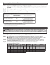
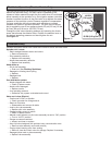
Step 10 – When installing the riser assembly to the sprinkler body, align the ratchet ring with the inside body rib. Use
the indicator on top of the sprinkler body to center the ratchet ring. See Figure 14.
9
Figure 12
Figure 13
Figure 14