


Service Procedures ________________________________________________________________
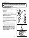
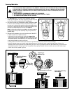
Servicing Sprinkler Mechanism
1. Remove the cap screw (1) and cap (3).
Note: During reassembly, ensure the cap is correctly installed with the
Toro Logo positioned over the main nozzle (10).
2. Insert hooked end of multi-purpose tool (P/N 996-83) into slot in snap
ring (13). Pull snap ring inward toward sprinkler assembly, then upward
to remove from groove.
Note: During reassembly, ensure snap ring is correctly installed and fully
seated in groove.
3. Insert hooked end of mult-purpose tool into slot provided in the nozzle
base above main nozzle. Pull riser assembly out of body.
4. While pushing seal/retainer assembly (14 and 15) downward to slightly
compress return spring, use a 1/2" nut driver (P/N995-80) to remove
nozzle base lock nut (8). Pull nozzle base assembly from drive assembly
shaft.
5.
Slowly release tension from return spring.
6. Remove the slotted stainless steel washer (7).
7. Three small tabs are provided on the edge of the multi-purpose tool.
Insert tabs into debris filter screen. Holding plastic base of riser
assembly, turn screen counterclockwise to remove.
8. Remove variable stator and stator support from riser assembly.
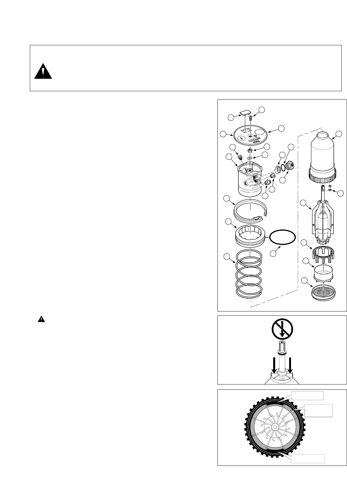
Note: The stator support is keyed to the riser assembly. During
reassembly, ensure stator support slots engage riser assembly
alignment tabs. Refer to Figure 7 for the location of the alignment tabs.
9. Using a 5/8" nut driver (P/N 995-99), unscrew main nozzle from nozzle
base assembly.
10. Using a 7/16" nut driver (P/N 995-79), unscrew two inner nozzles from
nozzle base assembly. Remove restrictor from one inner nozzle.
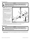
11. Pressing only on the ribbed area of drive assembly, push the drive
assembly out of riser assembly as shown in
Figure 6
CAUTION: When removing or installing the drive assembly,
DO NOT press on the threaded shaft or attempt to pull the drive
assembly out of riser assembly. Push on the ribbed areas only!
Failure to comply may cause separation of drive assembly
components.
Note:
The drive assembly is keyed to the riser assembly. During
reassembly, position the extra rib of the drive assembly to the right of
either alignment tab of the riser assembly as shown in Figure 7.
12. Thoroughly clean and inspect all parts and replace as necessary.
Reassemble in the reverse order.
8
Figure 6
Alignment Tab
Extra Rib Of
Drive Assy
Alignment Tab
Figure 7
23
22
21
20
19
18
16
15
14
14
1
2
4
8
9
10
11
12
5
7
6
3
3
Figure 5
WARNING
NEVER STAND OR LEAN OVER THE SPRINKLER WHILE THE IRRIGATION SYSTEM IS BEING FILLED,
DURING MANUAL OR AUTOMATIC OPERATION OR WHEN PERFORMING SPRINKLER SERVICE
PROCEDURES. DIRECT CONTACT WITH IRRIGATION SPRAY, A FAILED OR IMPROPERLY INSTALLED
SPRINKLER CONNECTION OR SPRINKLER COMPONENTS FORCIBLY EJECTED UPWARD UNDER
PRESSURE CAN CAUSE SERIOUS INJURY.