


2
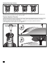
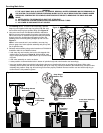
Connecting Hydraulic Control Tubing (Hydraulic Models Only)
1. Route control tubing from the controller
to the sprinkler location(s).
Note: Leave an 18" (45.7 cm) service
loop of tubing at each sprinkler to
facilitate movement of sprinkler and
service operations. Refer to Table 2
for tubing run length and sprinkler
elevation information.
2. Flush tubing thoroughly to remove all
air and debris.
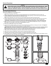
3. Remove the tube retainer and poly cap
from the tubing adapter at the base of
the sprinkler.
4. Slide the tube retainer over the end of the control tubing and attach tubing to adapter.
5. Slide tube retainer over the adapter area to secure tubing.
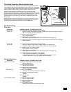
System Start Up _________________________________________________________________
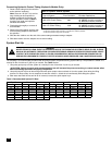
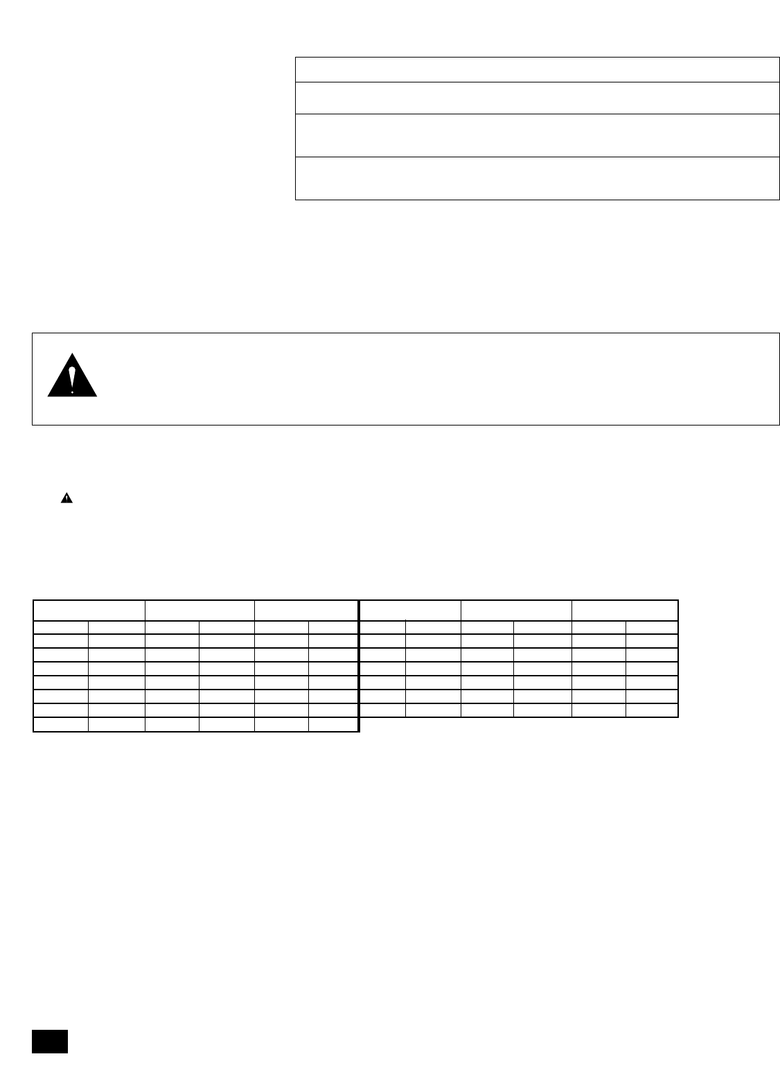
The following is a recommended procedure that will protect system components during system start-up. The procedure is based on a
velocity fill rate of less than 2' (0.61 m) per second. See Table 3 below.
1. Use jockey pump only to fill the system at a velocity fill rate of less than 2' (0.61 m) per second.
CAUTION: Failure to comply with recommended fill rate will increase line pressure resulting in a water hammer effect
that could damage sprinklers and piping components.
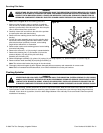
2. Use quick coupler keys at all tees and greens with quick coupler valves to bleed air from the system lines during the filling
process. For best results, do not compress air and then relieve it – bleed the air continuously while filling the system.
3. After water has filled all lines and all air is removed, remove the quick coupler keys.
Table 3: Recommended System Fill Rate
Table 2: Hydraulic Control Systems
Maximum Distance
Type of System* From Controller Elevation Restrictions
Normally Open (01) Valve elevation should not exceed
with 3/16" Control Tubing 500' 25' ABOVE controller elevation or
70' BELOW controller elevation.
Normally Open (01) Valve elevation should not exceed
with 1/4" Control Tubing 1000' 25' ABOVE controller elevation or
70' BELOW controller elevation
*• All hydraulic connections on Toro valves are
1
⁄4" insert type.
• Control line pressure must be equal to or greater than mainline pressure.
• Control line pressure range is 40 to 150 PSI.
Pipe Size Flow Velocity Pipe Size Flow Velocity
in. cm GPM LPM ft/sec m/sec in. cm GPM LPM ft/sec m/sec
1/2 1.3 2 7.6 1.60 0.49 3 7.6 45 170.3 1.86 0.57
3/4 1.9 3 11.4 1.92 0.59 4 10.1 75 283.9 1.87 0.57
1 2.5 5 18.9 1.50 0.46 6 15.2 150 567.8 1.73 0.53
1-1/4 3.1 10 37.9 1.86 0.57 8 20.2 250 946.3 1.70 0.52
1-1/2 3.8 10 37.9 1.41 0.43 10 25.4 450 1703.0 1.97 0.60
2 5.0 20 75.7 1.80 0.55 12 30.5 500 1893.0 1.55 0.47
2-1/2 6.4 30 113.6 1.84 0.56
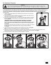
WARNING
NEVER STAND OR LEAN OVER THE SPRINKLER WHILE THE IRRIGATION SYSTEM IS BEING FILLED, DURING
MANUAL OR AUTOMATIC OPERATION OR WHEN PERFORMING SPRINKLER SERVICE PROCEDURES. DIRECT
CONTACT WITH IRRIGATION SPRAY, A FAILED OR IMPROPERLY INSTALLED SPRINKLER CONNECTION OR
SPRINKLER COMPONENTS FORCIBLY EJECTED UPWARD UNDER PRESSURE CAN CAUSE SERIUS INJURY.