


Connecting Electric Control Wires
1. Route control wires to sprinkler location(s). Provide
enough extra wire at sprinkler to allow for
movement of sprinkler without straining wire
connections. One common wire and one station
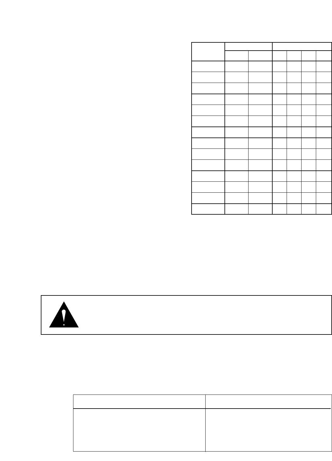
wire are required for each sprinkler. See Wire
Sizing Chart, Table 1 for proper application.
2. Attach control wires to solenoid leads using an
approved waterproof splicing method.
CAUTION
All wires must be waterproofed to prevent short
circuit to ground and subsequent controller
damage.
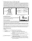
Connecting Hydraulic Control Tubing
1. Route control tubing from controller to sprinkler
location(s).
Note: Leave an 18 inch service loop of tubing at
each sprinkler to facilitate movement of sprinkler and
service operations. Tubing runs in excess of 1,000
feet are not advisable due to delayed response time.
The controller for hydraulic valve-in-head systems
should never be located more than 25 feet below or
more than 70 feet higher than the valves. Although
there is no limit to the amount of hydraulic valve-in-
head sprinklers controlled by one control station,
practical experience suggests the maximum number
of heads normally used is five.
2. Flush tubing thoroughly to remove all air and debris.
3. Remove tube retainer and poly cap from tubing
adapter at base of sprinkler.
4. Slide tube retainer over control tubing and attach tubing to adapter. Slide tube retainer over adapter area to
secure tubing.
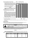
System Start-Up
The following is a recommended procedure that will protect system components during system start-up. The
procedure is based on a velocity fill rate of less than 2 feet per second. See Table 2 below.
1. Use jockey pump only to fill system at velocity fill rate of less than 2 feet per second.
2. Use quick coupler keys at all tees and greens with quick coupler valves to bleed air from system lines
during filling process. Do not compress air and then relieve - bleed air while filling system.
3. After water has filled all lines and all air is removed, remove quick coupler keys.
CAUTION
Failure to comply with recommended fill rate will increase line pressure resulting in a water hammer
effect that could damage sprinklers.
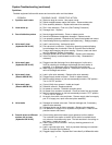
Table 2
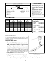
VOLTAGE WIRE SIZE NUMBER OF VALVES
AT
CONTROLLER CONTROL COMMON 1 2 3 4
110 VAC 14 14 2348 1012 549 353
110 VAC 14 12 2890 1239 673 433
110 VAC 14 10 3378 1448 786 505
110 VAC 12 12 3759 1604 873 561
110 VAC 12 10 4591 1973 1071 688
110 VAC 12 8 5411 2328 1263 812
110 VAC 10 10 5945 2555 1387 892
115 VAC 14 14 2765 1309 846 549
115 VAC 14 12 3393 1608 1039 673
115 VAC 14 10 3962 1877 1213 783
115 VAC 12 12 4394 2082 1346 872
115 VAC 12 10 5397 2557 1652 1071
115 VAC 12 8 6364 3018 1949 1263
115 VAC 10 10 6986 3311 2140 1387
Table 1 - Wire Sizing Chart
Maximum Allowable Length in Feet From Controller to VIH Sprinklers.
Chart based on the following: Transformer - 115 VAC - 124 VAC, 45 VA
Coil Assy. - 24 VAC, 60 Hz
Holding - .21 Amps
In Rush - .42 Amps
3
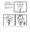
WARNING
TO PREVENT PERSONAL INJURY, DO NOT STAND DIRECTLY OVER ANY
COMMERCIAL OR LARGE TURF HEAD DURING FILL OR WHEN ACTIVATING
MANUALLY AT THE HEAD.
Pipe Size Gallons Per Velocity - Feet Pipe Size Gallons Per Velocity - Feet
Inches Minute Per Second Inches Minute Per Second
1/2 2 1.60 3 45 1.86
3/4 3 1.92 4 75 1.87
1 5 1.50 6 150 1.73
1-1/4 10 1.86 8 250 1.70
1-1/2 10 1.41 10 450 1.97
2 20 1.80 12 500 1.55
2-1/2 30 1.84