


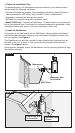
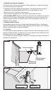
v Connect RainSensor Wiring:
Route the RainSensor connection wire into the timer through the access hole in
the base of the timer cabinet.
Note: Avoid routing the wire over any sharp edges where damage to the wire
insulation may occur. For best results, hide the wire as much as possible by
tucking it under shingles and/or moldings. Seal any holes made by passing the
wire through structure walls.
Caution: To prevent severe equipment damage, never connect the
RainSensor to any power source greater than 24 VAC. If you are in doubt,
contact a qualified installer or electrician.
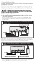
1. Disconnect power to the timer.
2. Use one of the following connection methods A, B or C, that best suits the
timer model configuration.
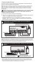
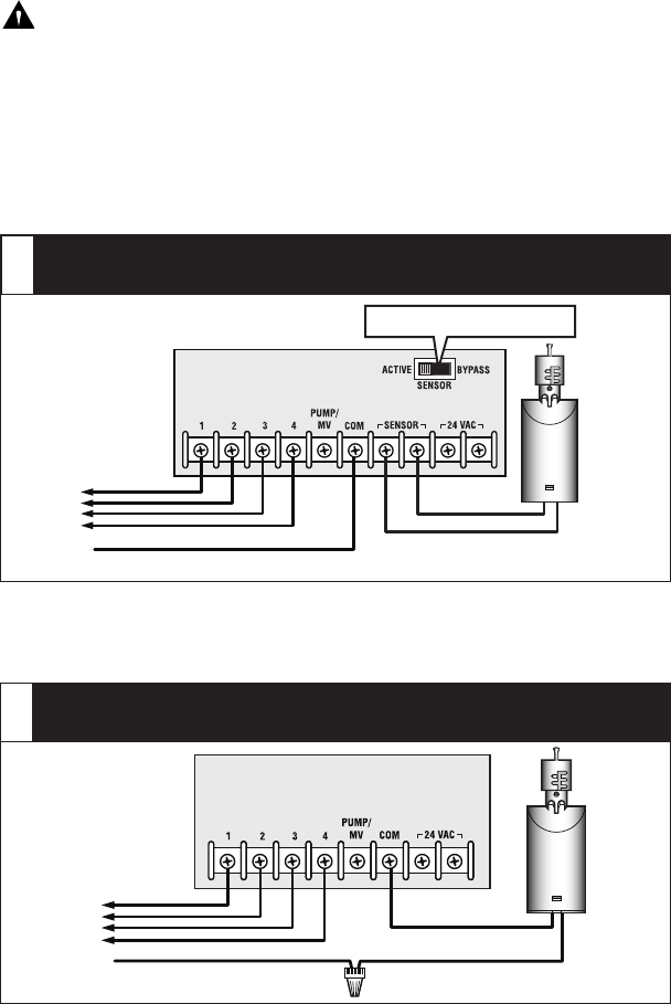
• Find the controller sensor terminals (generally marked “SENSOR”, “SEN”
or “S”) and attach the RainSensor control wires directly to these terminals
(in either order).
Note: There may be a jumper wire connecting the two Sensor wire terminals
that must be removed when connecting the RainSensor. Also, place the Sensor
Bypass switch in the Active position for sensor-controlled operation.
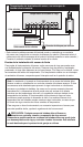
• Remove the valve common wire(s) from the valve common wire terminal and
join to one RainSensor wire lead using a twist-on wire connector. Attach the
remaining RainSensor wire lead to the valve common terminal.
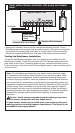
Common Wire From Valves
Timer with Sensor terminals, with or without pump start/
master valve:
A
Sensor Bypass Switch
Common Wire From Valves
To Valves
Twist-on Wire Connector
Irrigation System Timer
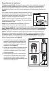
Timer without Sensor terminals or pump start/ master
valve:
B
To Valves