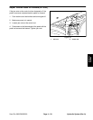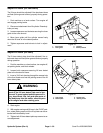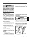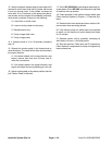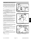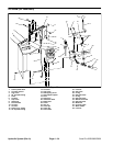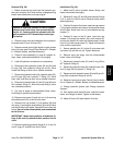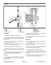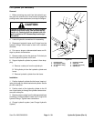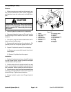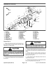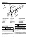
Removal (Fig. 26)
1. Before removing any parts from the hydraulic sys-
tem, park machine on a level surface, engage parking
brake, lower attachment, and stop engine.
CAUTION
draulic oil. Controls must be operated with the
tion switch.
Operate all hydraulic controls to relieve system
pressure and avoid injury from pressurized hy-
ignition switch in OFF. Remove key from the igni-
2. Remove cover from the midsection of the machine.
Unscrew knob (5) from lift lever (20).
3. Remove control panel (right fender) to gain access
to the lift valve (see Control Panel Removal in Chapter
6 – Wheels, Brakes, and Miscellaneous).
4. Clean lift valve assembly (11) and all hydraulic fit-
tings, tubes, and hoses attached to it thoroughly.
5. Label all hydraulic connections for reassembly.
6. Disconnect both hydraulic hoses (32 and 33) and
O–rings (29) from hydraulic fittings (8 and 9). Allow
hoses and fittings to drain into a suitable container.
7. Disconnect hydraulic hose (34), hydraulic tube (35),
and O–rings (26) from hydraulic T–fitting (10). Allow
hose, tube, and fitting to drain into a suitable container.
8. Disconnect hydraulic tube (31) and O–ring (26) from
90
o
hydraulic fitting (2). Allow tube and fitting to drain
into a suitable container.
9. Put caps or plugs on disconnected hoses, tubes,
and fittings to prevent contamination.
10. Remove cap screw (3) and lock nut (14) securing
the welded pivot (21) to the lift valve stem.
11. Remove four cap screws (7), lock washer (24) and
lock nuts (1) securing the pivot bracket (6) to the lift valve
and the lift valve to the frame. Separate lift valve from the
frame. Do not further disassemble parts assembled
to the lift lever.
IMPORTANT: Match mark positions of hydraulic fit-
tings (2,8,9 and 10) relative to their ports on the lift
valve.
12. Remove remaining hydraulic fittings (2, 8, 9, and 10)
and O–rings (27 and 28) from the lift valve.
Installation (Fig. 26)
1. Make sure lift valve, hydraulic hoses, fittings, and
tubes are cleaned thoroughly.
2. Reinstall O–rings (27 and 28) and hydraulic fittings
(2, 8, 9, and 10) to the lift valve. Observe match marks
when tightening.
3. Position lift valve to the frame. Insert two cap screws
(7) through the bottom two holes of frame bracket frame
and lift valve. Screw lock nuts (1) to the bottom two cap
screws (7).
4. Position lift lever to the lift valve. Insert two cap
screws (7) through flat washer (24), pivot bracket (6),
and top two holes of lift valve and frame bracket. Screw
lock nut (1) to the top cap screw (7). Tighten all three lock
nuts and four cap screws.
5. Secure welded pivot (21) to the lift valve stem with
cap screw (3) and lock nut (4). Tighten fasteners.
6. Remove caps and plugs from the disconnected
hoses, tubes, and fittings
7. Reconnect hydraulic tube (31) and O–ring (26) to
90
o
hydraulic fitting (2).
8. Reconnect hydraulic hose (34), hydraulic tube (35),
and O–rings (26) to hydraulic T–fitting (10).
9. Reconnect both hydraulic hoses (32 and 33) and O–
rings (29) to hydraulic fittings (8 and 9).
10. Reinstall control panel (see Control Panel Installa-
tion in Chapter 6 – Wheels, Brakes, and Miscellaneous).
11. Charge hydraulic system (see Charge Hydraulic
System).
12. Run machine and check lift valve, hydraulic hoses,
tubes, and fittings for leaks. Tighten as necessary.
13. Adjust lift lever (20) (see Adjust Lift Lever).
Hydraulic
Systems
Sand Pro 2020/3020/5020 Page 4 – 37 Hydraulic System (Rev. A)


