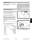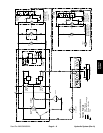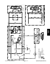
Retract and Extend Lift Cylinder
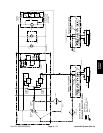
The hydraulic lift circuits for the SP 2020/3020 and SP
5020 function identically. Each machine has identical
charge pumps, lift valves, and lift cylinders. These com
-
ponents are the heart of the lift circuit.
In addition to replenishing the closed loop circuit with
fluid from the tank, charge pump (P2) flow in excess of
replenishment requirements is relieved through the
charge relief valve (R2). Fluid returns through the lift
valve and back to the tank. This excess flow is used to
operate the lift cylinder.
The charge pump is a fixed displacement gerotor pump
that is driven directly off the traction pump (P1). It has
sufficient output to handle intermittent operation of the
lift cylinder under load. The implement relief valve (R1)
in the charge circuit allows high enough pressure to op
-
erate the lift cylinder with attachments, and protects the
charge pump.
When the lift lever to the lift valve is in the neutral posi-
tion, fluid flow from the charge pump is bypassed around
the lift cylinder through the lift valve. Fluid returns to the
tank as a normal part of the charge and bleed off circuits.
Moving the lift lever to the lift position allows the lift valve
to direct fluid flow from the charge pump into the rod side
of the piston. The piston moves into the cylinder pushing
fluid out the piston end of the cylinder and to the tank. As
the cylinder rod retracts, the attachment is raised. When
the lift lever is released, the lift valve returns to the neu
-
tral position. The attachment is held in its present posi-
tion.
Moving the lift lever to the lower position allows the lift
valve to direct fluid flow from the charge pump into the
piston side of the cylinder. The piston moves out of the
cylinder pushing fluid out the rod end of the cylinder and
to the tank. As the cylinder rod extends, the attachment
is lowered. When the lift lever is released, the lift valve
returns to the neutral position. The attachment is held in
its present position.
Excessive load on the lift cylinder causes circuit pres-
sure to increase and the implement relief valve (R1) to
dump directly to the tank. This condition happens in both
the lift and lower modes.
Hydraulic System (Rev. A) Page 4 – 12 Sand Pro 2020/3020/5020


