


Assembly Section 2-4
ASSEMBLY
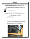
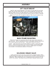
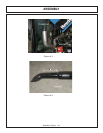
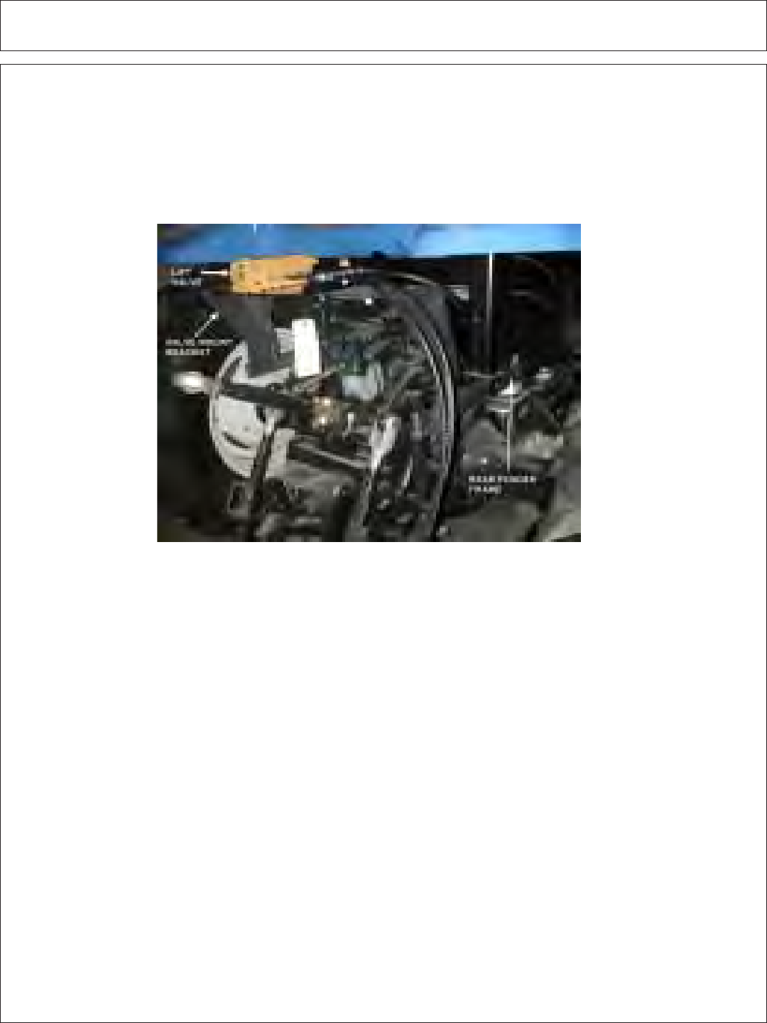
LIFT VALVE MOUNT
Install the valve mounting bracket to the inside of the right and left rear fender
frame tube as shown below. Align the valve mounting plate with the drilled holes.
Mark the center of one of the holes above and in line with the slotted holes in the
valve plate. Do not use any holes that will be used to mount the valve on the plate.
Mount the lift valve with the supplied hardware. Refer the parts section for the
details.
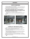
MAIN FRAME MOUNTING
Raise front of tractor as needed and slide the main frame under tractor from
right hand side. With an overhead hoist and / or jack-stands, raise the frame up to
the correctly matching mounting holes. Install spacer blocks and shims as
needed. Install cap-screws and all other hardware as shown in main frame parts
section. Remove the cap-screws one at a time and apply a thread locking agent,
then reinsert the cap-screws and tighten / torque to values noted in the torque
chart located in the maintenance section of this manual.
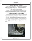
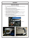
SOLENOID BRAKE VALVE
Install a solenoid valve the mounting bracket with the supplied hardware. While
installing fittings to the brake valve, the electrical coil on the spool must be removed to
make room. When reinstalling the coil, it is important to use no more than 5 ft. lbs.
(or 60 in. lbs.) torque. Over torque to the coil will result in hydraulic failure of spool.