


Assembly Section 2-3
ASSEMBLY
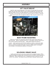
ADJUSTING REAR WHEELS
Raise rear of tractor onto jack-stands. Follow the instructions in the tractor
owners manual for adjusting tires and rims to 72” center for side mounted
mowers and 79.8” for boom mowers. NOTE: This may require switching the
wheels to opposite sides of tractor.
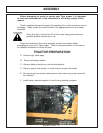
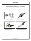
CRANKSHAFT ADAPTER
If necessary remove the four cap-screws from the crankshaft pulley. Then
install the crankshaft adapter and spacer to the pulley with cap-screws and lock-
washers as shown in the parts section.
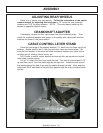
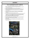
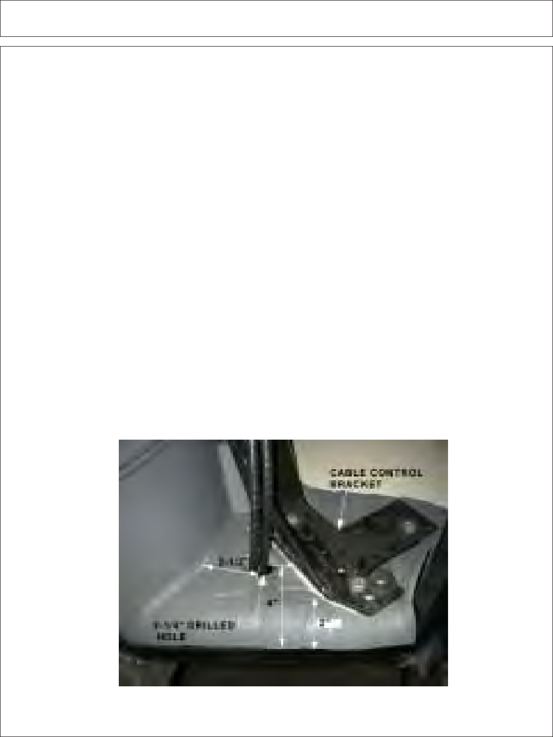
CABLE CONTROL LEVER STAND
Place the front edge of the support bracket 2 ¾” back from the lower right front
window. Rotate stand to be 2” from the right door frame as shown below. Be
sure that the location of the stand will allow clearance between the cable control
handles and all existing interior levers, etc.
Drill 3 holes to match control bracket and secure with cap-screws and nylock
nuts noted in parts section.
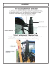
Cut a 2 ¼” hole in the floor from inside the cab. This hole is to be located 2-1/2”
up from floor, and 4” from the metal edge by the right door. Install trim lock around
the metal edges of the hole, then route the cables through the hole. Next, wrap the
cables with the 6” split hose at the point they pass through the hole, and secure with
zip-ties.