SECTION III.
FUNCTIONAL CHECK PROCEDURES
4-10. FUNCTIONAL CHECK PROCEDURES
This section deals with normal functional check procedures, and in-
cludes all steps necessary to ensure the Turbo Start 4100 is func-
tioning within specific operational parameters prior to operational
use. As users gain experience with the Turbo Start 4100, they will
incorporate these functional checks as a routine practice.
4-11. REQUIRED EQUIPMENT FOR FUNCTIONAL CHECK.
FLUKE OR EQUIVALENT TYPE DIGITAL MULTIMETER.
4-12. DC FUNCTIONAL CHECK.
1. CHECK UNIT FOR EVIDENCE OF DAMAGE - Check for dents, punctures,
case distortion or misalignment, cracked or loose connectors. If no
damage is evident proceed to step two.
IF DAMAGE IS EVIDENT contact distributor or manufacturer.
2. ENSURE UNIT IS NOT PLUGGED INTO 208-240 VDC. Unplug AC power if
plugged in.
3. CHECK UNIT INTERNAL RESISTANCE (TEST FOR SHORTS) - Better than 10
Megohms. Ensure no short exists.
Negative (-) DC receptacle terminal and unit case.
Positive (+) DC receptacle terminal and unit case.
4. CHECK DC VOLTAGE READING AT DC RECEPTACLE TERMINALS.
24 to 25.5 VDC depending on state of charge.
5. PLUG IN 208-240 POWER CORD.-Ensure power unit is connected to a
suitable AC power source 208-240 Single Phase 50/60 Hz.
6. CHECK UNIT FOR STATE OF CHARGE -
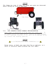
Unit shall be in horizontal
position to ensure unit’s vent ports are free from blockage
. After
approximately 5-8 seconds, unit LED status indicator shall illuminate
indicating power cell state of charge. Ensure LED status indicator
and cooling fan are operational. Prior to continuing to step 7, the
LED status indicator should show a single green bar (last LED bar) to
indicate the unit’s power cells are fully charged. Also under full
charge the fan will ratchet but not enable.
4−7


