


Model 2002 Vacuum Gauge Page 16 of 37
4.3. TTL Outputs
TTL outputs are provided for process control. High and Low set points are entered on the front panel (see
Section 3.4) and TTL signals are generated on the I/O cable in the following manner:
1. When the pressure as indicated by the Model 2002 is above the High set point, the High signal line (pin #3) will
be set to a TTL high level (+5 VDC). When the indicated pressure is below the High set point, the High signal
line (pin#3) will be set to a TTL low level (+0 VDC).
2. When the pressure as indicated by the Model 2002 is below the Low set point, the Low signal line (pin #4) will
be set to a TTL high level (+5 VDC). When the indicated pressure is above the Low set point, the Low signal
line (pin #4) will be set to a TTL low level (+0 VDC).
These TTL signals are used for a variety of applications. With these signals, the user has the capability to
turn off/on various equipment such as valves, flow controllers, pumps, heaters, and safety equipment.
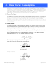
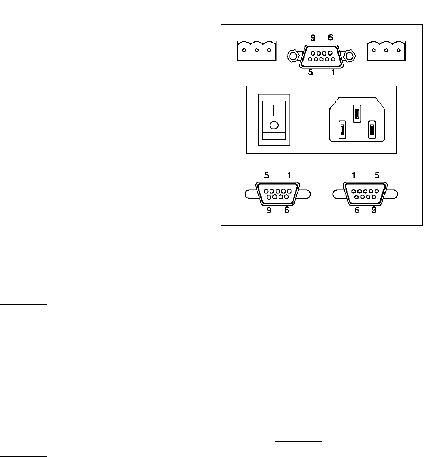
4.4. Power Entry Module
The AC power for the Model 2002 enters the
instrument through a power entry module that
contains a fuse, on/off switch and an IEC 320 power
inlet.
The fuse is rated for 250 V, 1/4 A. It can be
accessed by unplugging the AC cord and prying the
fuse compartment open with the tab and slot in the
power inlet chamber. There is a spare fuse in the
compartment within the fuse holder.
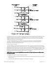
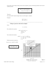
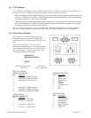
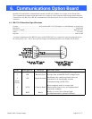
A
nalog 0-10V OPTION
BOARD CONNECTOR
Pin# Connection
1 Analog Out 1 (1024 Torr) High
2 Analog Out 1 (1024 Torr) Shield
3 Analog Out 1 (1024 Torr) Low
4
5
6
7 Analog Out 2 (1000 mTorr) Low
8 Analog Out 2 (1000 mTorr) High
9 Analog Out 2 (1000 mTorr) Shield
4-20mA OPTION
BOARD CONNECTOR
Pin# Connection
1 I-Loop Out (+) 1024 Torr
3 I-Loop In (-) 1024 Torr
8 I-Loop Out (+) 1000 mTorr
7 I-Loop In (-) 1000 mTorr
SENSOR CONNECTOR
Pin# Connection
1 Sensor
2 Bridge (sense)
3 Bridge-Power
4 Reference
5 Common
6 Common (sense)
7 N/C
8 N/C
I/O CONNECTOR
Pin# Connection
1 Analog Output
2 Analog Common
3 High Setpoint
4 Low Setpoint
5 Digital Common
6 Remote Zero
7 +5V
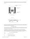
Model 2002
Rear Panel Detail
Fig 4.2
TRANSDUCER CONN.
(FEMALE)
STANDARD
I/O CONNECTOR