www.tanaka-usa.com 8 custsvc@tanaka-ism.com
Owner’s Manual
TBC-250/250PF/PFD,TBC-2501,TBC-2510,TBC-270PF/PFD
-
-
-
-
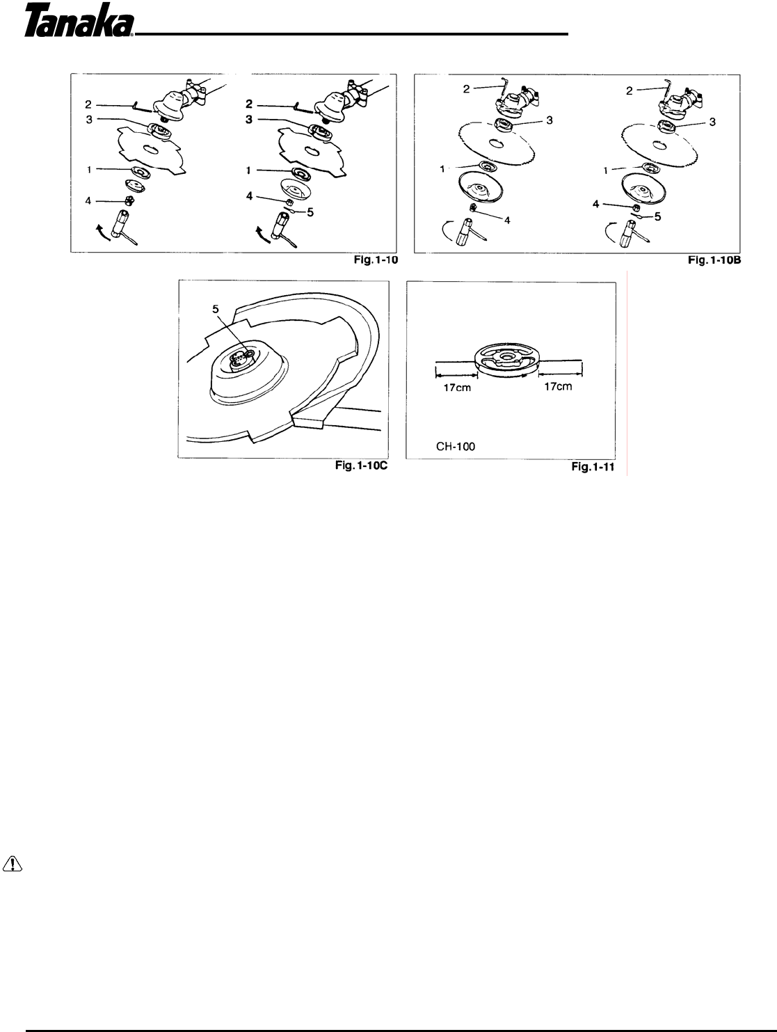
Installation of cutting blade (Fi
. 1-10, 10B) (If so equipped)
When installing a cutting blade, make sure the blade is not cracked or damage and the cutting edges are facing the correct
direction.
NOTE!
When installing cutter holder cap (1), be sure to set the concave side toward the blade.
Insert the allen wrench (2) into the hole of the gear case in order to lock the cutter holder (3). Please note that the cutter
fixing bolt or nut (4) has left handed threads ' (clockwise to loosen/counter-clockwise to tighten). Tighten the fixing bolt or nut
with the box wrench.
NOTE!
If your unit is of a nut-securing type, the blade must be retained with a new cotter pin (5) each time installed. (Fig. 1 -10C)
CAUTION!
Before operation, make sure the blade has been properly installed.
CAUTION!
If your unit is equipped with protection cover under a cutting blade, check it for wear or cracks before operation. If any
damage or wear is found, replace it.
Installation of the cutting head
NOTE!
For installation see your Cutting Head Owner's Manual, provided with the unit.
WARNING!
For TANAKA heads, use only flexible, non-metallic line recommended by the manufacturer. Never use wire or wire-ropes.
They can break off and become a dangerous projectile.
NOTE!
When using TANAKA alloy head (CH-100), initial cutting line length should be about 17cm (6-3/4”) each. (Fig. 1 -11)


