www.tanaka-usa.com 5 custsvc@tanaka-ism.com
Owner’s Manual
TBC-250/250PF/PFD,TBC-2501,TBC-2510,TBC-270PF/PFD
-
-
-
-
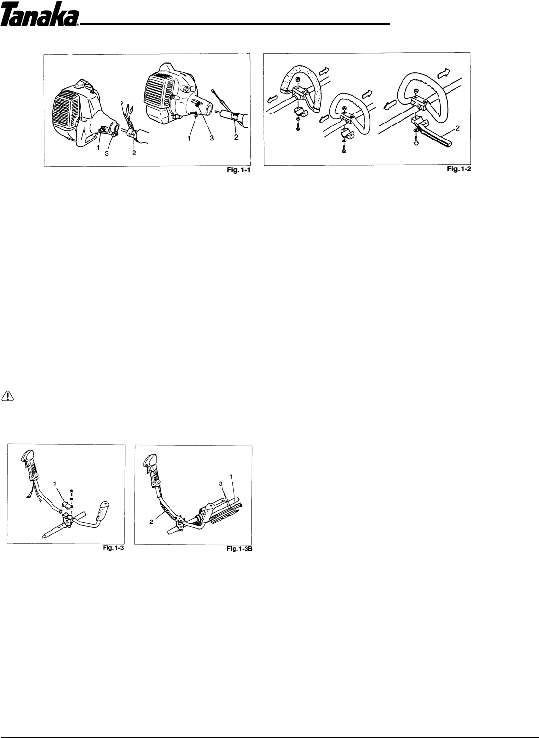
3. Assembly procedures
Drive shaft to engine (Fig. 1 -1)
Loosen tube locking bolt (1) about ten turns so that the bolt point will not obstruct drive shaft tube to be
inserted. When inserting drive shaft tube, hold the tube locking bolt outward preventing inside fitting from
obstructing as well.
Insert the drive shaft into the clutch case of the engine until the decal (2) on the drive shaft tube meets the
clutch case.
NOTE!
If the pipe will not go in far enough this is because the shaft end is not lined up with the receiver. In this case,
turn the drive shaft (at the opposite end of the pipe) while pushing the pipe toward the engine. Tighten the
tube-locking (1) bolt by lining up the hole in the shaft tube. Then tighten clamp bolt securely (3).
Installation of handle (Fig. 1-2)
WARNING!
When you use steel/rigid blades on straight shaft trimmers or brush cutters, always use barrier bar (2) and
shoulder harness with the loop handle. (Fig. 1 -2)
Attach the handle to the drive shaft tube with the angle towards the engine.
Adjust the location to the most comfortable position before operation.
Remove the handle bracket (1) from the assembly. (Fig. 1 -3)
Place the handles and attach the handle bracket with four bolts lightly. Adjust to appropriate position. Then fix it
firmly with the bolts.
Put stop cords (3) and throttle wire (1) through protective tube (2), then unhook the hip pad. (Fig. 1-3B)


