


SECTION 2
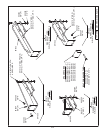
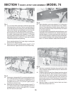
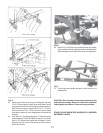
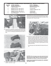
1a. The above 29’ JD1610 chisel plow is shown with a 4 bar mounted
harrow using M74 carrier arms. Two 7’ sections were used in the
center and one 8’ section was used on each wing. An optional
method is to use one 14’ section in the center with 3 carrier arms.
Wing section sizes will vary with the width of the chisel plow.
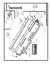
2a. Position frame mounting brackets on the frame as shown above.
All measurements are from bracket center to bracket center. Again
spacing on wing sections will vary with the width of the chisel
plow.
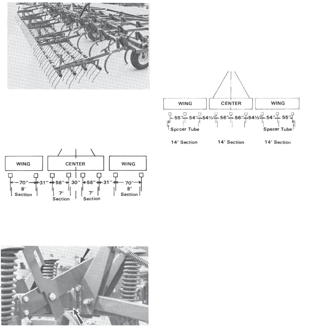
3a. The fi rst mounting bracket on each wing is located under a brace
and needs special spacers (see arrow) and longer bolts for
mounting. Summers JD1510 Chisel Plow mounting package (PN
8H1590) includes 8 spacer plates and 16 - 5/8 x 7” bolts. Spacer
plates are also supplied for use on the outer mounting bracket on
each wing so sections run perfectly square.
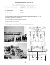
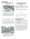
SPECIAL BRACKETS FOR JD1610
CHISEL PLOWS
MOUNTING INSTRUCTIONS
FOR SUMMERS MOUNTED HAR-
ROWS
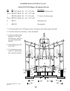
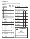
Shown below is the layout of mounted harrows on a 41’ JD610 Chisel
Plow (over center fold with 12” shank spacing). Three 14’ sections are
used with three model 74 carrier arms per section. Two spacer tubes
for lateral positioning are recommended (order Summers PN 8H1502
for one spacer tube).
An optional method is to use two 7’ sections in place of one 14’ section.
Also, wing section sizes will vary with the width of the chisel plow.
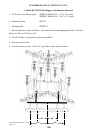
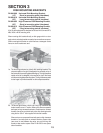
SPECIAL NOTES REGARDING
JD610 MOUNTING:
1. Frame mounting brackets on the center frame cannot be more
than 56” from the machine center-line or they will interfere with the shank
standards when wings fold over center.
2. On the above layout, all lever linkage assemblies mount two
teeth in from the end of a section. Again, this may vary with different
size machines and sections.
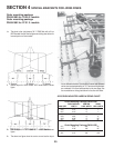
3. When the wings of the chisel plow are folded to transport
position, they go over center and the top ends touch each other (41’
model).
To limit the travel of the mounted harrow sections as they
fold over center with the chisel plow wings, the lock collars located on
the 3/4” dia. support rods should be slid down 3” on the rod and locked
in place with a 7/16 x 1” set screw and nut. This should be done on all
three support rods per wing (41’ model). This adjustment is necessary
on all size models where top ends of wings touch each other.
4. With the above adjustment, mounted harrow sections may still
touch each other; however, the contact should be reduced to a point
where no parts bend or get permanently tangles.
18