


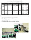
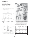

JD235 DISK FRAME MOUNTING BRACKET SELECTION CHART
Bracket 19-26 Ft. Models 27-31 Ft. Models
No. Bracket Description Bracket Description
1 Long Hi-Clearance Short Hi-Clearance
2 Modifi ed Short Univ. (See Fig. 3a) Long Universal
3 Modifi ed Short Univ. (See Fig. 4a) Long Univ. & Extension Tube
4 Modifi ed Short Univ. (See Fig. 4a) Long Universal
5 235 Bracket & Spacer Tube (Fig. 5a) Long Universal
6 Short Hi-Clearance Short Hi-Clearance
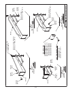
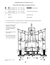
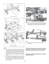
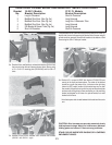
3a. Bracket #2 is a modifi ed short universal disk bracket (PN 8H1546)
that mounts to the disk main frame as shown above. Secure using
a 1/2 x 5 x 6-1/8” mounting plate (PN 8H1340) and four 5/8 x 8”
bolts.
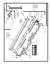
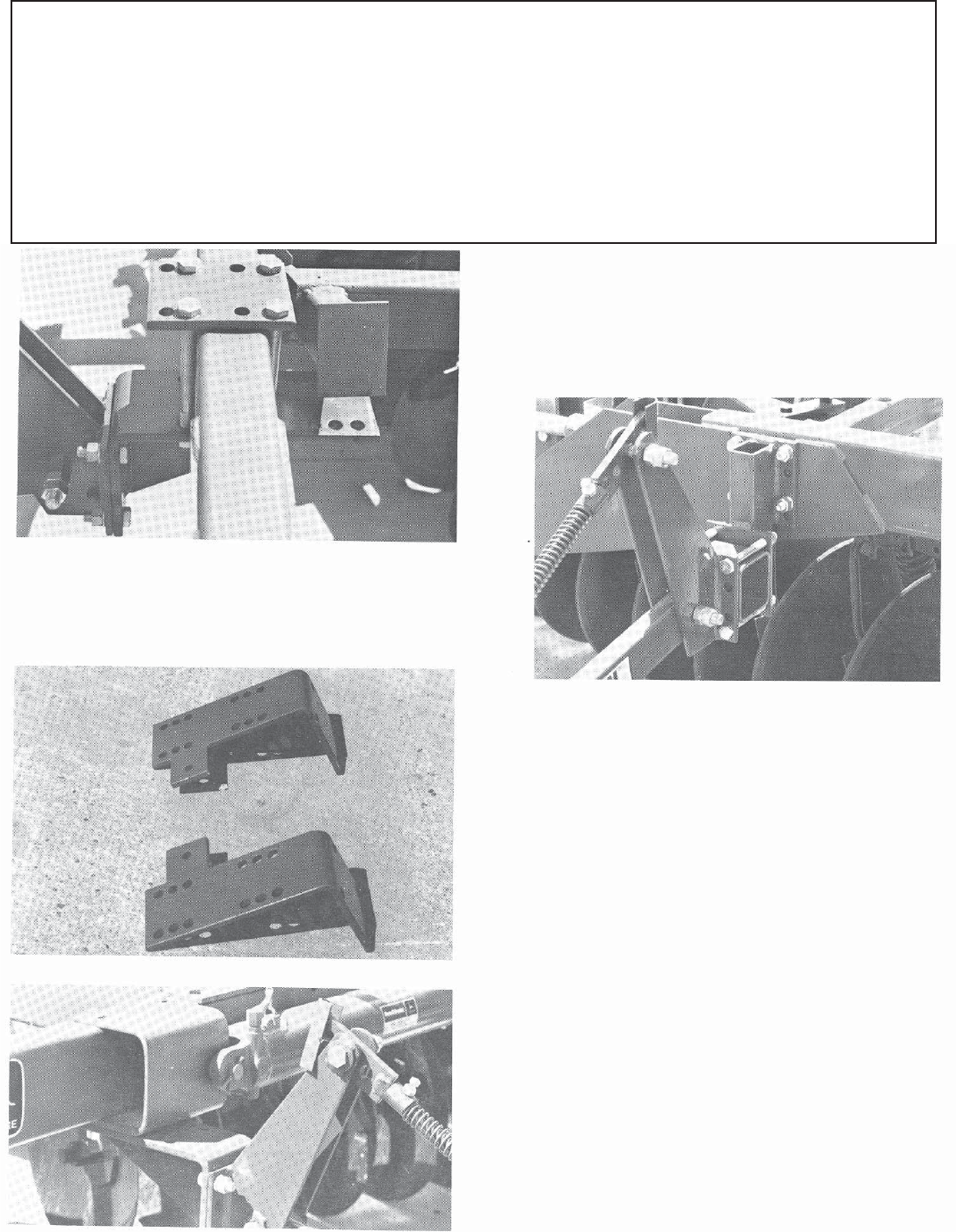
4a. Brackets #3 and #4 are modifi ed short universal disk brackets
(8H1540 – left, 8H1541 – right).
These brackets bolt to a disk frame using existing holes in the frame. On
the left side, the two bolts securing the anchor end of the rear wing lift
cylinder must be removed. Secure both brackets to the bottom of disk
frame using two 5/8 x 8” bolts per bracket.
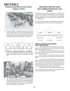
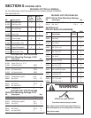
5a. Bracket #5 is a special JD235 disk bracket (PN 8H1550) and
mounts to the frame as shown above. The center of the bracket
should line up with the center of the 1st brace on the right wing
(shown for 22’9” model, location of this bracket may vary on other
size models). Mount fl ush on top with the outer reinforcement plate
and secure by drilling holes in frame and bolting on. Use mounting
bracket as template for drill holes. An optional method is to weld
bracket to disk frame.
Note that a spacer tube is used between this bracket and the carrier
arm.
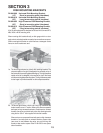
CAUTION: After harrows are securely mounted, slowly
fold implement wings. Watch for interference between
folding parts and correct if there are any problems.
STAND CLEAR WHENEVER RAISING OR LOWERING
IMPLEMENT WINGS.
21