


SECTION 1 BASIC LAYOUT AND ASSEMBLY; MODEL 74
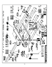
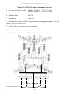
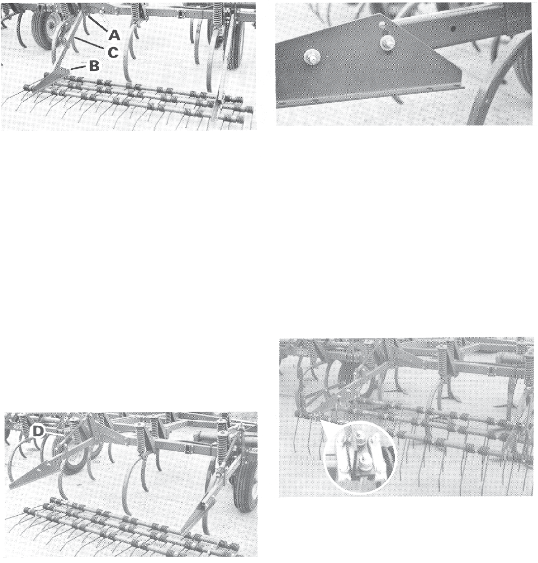
Fig. 1
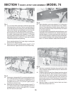
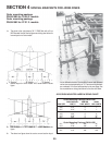
1a. Lay out all bars behind implements to determine approximate
mounting locations on the frame. Position mounting brackets (A)
on the implement frame so that they line up with spaces between
teeth on a bar. Brackets may be positioned one, two or three teeth
in from the end of a bar and may be different on both ends.
Mounting brackets (A) should be spaced as close as possible to
the number of teeth between them multiplied by 14”. (Example:
mounting brackets should be spread at 70” for a section with 5
teeth between brackets). A variation of 3” either way is allowable
if interference prevents exact positioning.
Secure mounting brackets (A) to frame using a mounting plate
and four 5/8” x 6” bolts per bracket.
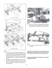
1b. Attach carrier arms (C) to mounting brackets using 3/4” x 3-1/2”
bolts and locknuts. Tighten locknut so arm can still pivot freely.
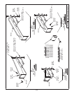
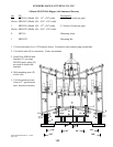
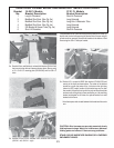
Fig. 2.
2a. Attach support rod assemblies (D) to mounting bracket and carrier
arms. Install cast swivel with long tube on top and attach to carrier
arm using a 3/4 x 3-1/2” bolt and locknut. IMPORTANT: Do not
overtighten locknut on 3/4” x 3-1/2” pivot bolt. Tighten locknut so
cast swivel can still pivot freely.
2b. Attach other end of support rod to mounting bracket using a 3/4” x
3-1/2” bolt and locknut. Install in middle height adjustment hole for
average implement. At this time, also install 7/16” x 1” set screw
with 7/16” hex nut into lock collars.
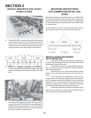
Fig. 3.
3a. Attach side plates to carrier arms using two 1/2 x 3” bolts per arm
(use a heavy fl at washer on each side). Mount in front, middle or
rear set of holes depending on desired clearance between front
harrow bar and implement. Place in second hole up from bottom
for initial level adjustment.
If mounting brackets are spaced at the calculated distance, mount
side plates on the same side of lift arms. If spaced more than the
calculated distance, mount both side plates on the inside lift arms
and if mounted brackets are spaced less than the calculated dis-
tance, mount both side plates on the outside of the lift arms. Spacer
tubes 1-1/2” thick are available if needed. Order PN 8H1502.
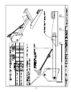
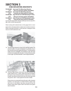
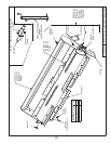
Fig. 4.
4a. Attach bars to underside of side plates using round U-bolts. Install
nuts on underside of fl ange as well as on top so U-bolts are solid
but pipe is free to turn.
4b. All sections require two sets of lever linkages (second set optional
on 3’6” and 4’8” sections). Mount levers as close as possible to
side plates and on the outside if possible to prevent excessive
torsion of the bars. For proper alignment of levers, each bar must
have the same number of teeth extending past the side plates.
See the following fi gures for correct lever linkage assembly of 2,
3 & 4 bar units.
4c. Attach pipe clamps on one end of rear bar. Attach one of each
side of side plate (see inset Fib. 4).
16