Troubleshooting and Servicing
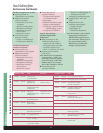
Six Step Troubleshooting
The following six step method of troubleshooting will save time and effort in the
diagnosis and analysis of air conditioning problems. It provides a logical approach
to solving the problem, not just treating the symptoms. The steps are as follows:
➊ Verify the problem (Operational check)
Check that the problem does exist.
Are components inoperable or malfunctioning?
➋ Determine related symptoms (Operational check)
Identify other symptoms that exist.
Are other circuits and components affected?
Do the related symptoms always occur with the primary symptom?
➌ Isolate the problem
Use the split half technique, the wiring diagrams, the troubleshooting
trees, appropriate model year service manuals, and manufacturer’s
manuals to locate the problem.
➍ Identify the cause of the problem
Is a circuit grounded?
Proper vacuum not available?
Belt alignment and/or tension improperly adjusted, or is a
component defective?
➎ Repair and/or replace
Defective wiring, vacuum lines, and components as required.
Confirm proper adjustment of components as required.
➏ Verify operation
Check the system to verify that the problem has been solved.
Ensure that all system components operate properly under standard
operating conditions according to technical specifications.
Also check related systems for proper operation.
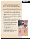
Quick Touch Method
An important step in troubleshooting air conditioning systems is to use the
quick touch method. Very briefly touch the components and tubing on the high
side and the low side of the system. High side components should feel warm
or hot to touch, while the low side components should feel cool to the touch.
Exercise caution when performing this procedure on high side of the system. The
tubing and components may be hot enough to cause minor burns. Do not touch
or hold for extended periods of time.
Note: If a component on the high side of the system located before the Thermal
Expansion Valve is cool or cold, this is an indication of a restriction.
Servicing
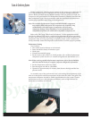
Manifold Gauges
The manifold gauges measure the pressures of the low side or suction side and
the high side or discharge side of the system. The gauges are calibrated in “psi for
pressure” and “inches of mercury for vacuum”. Note that zero (0) psi is equal to sea
level or 14.7 psi, or the pressure at the altitude level at which the gauge is being used.
The gauge set consists of the valve body, the connectors for the low pressure,
charge or evacuation, and high pressure hoses, and the gauges. The service valves
are infinitely adjustable between fully open and fully closed.
Quick Touch Method
Manifold Gauges
7


