


PAGE 26 — STOW G-2.9R A.C. GENERATOR— OPERATION & PARTS MANUAL — REV. #1 (10/28/04)
6. If the engine has started, slowly return the choke lever
(Figure 12 ) to the
“OPEN”
position. If the engine has not
started repeat steps 1 through 5.
7. Before the generator is placed into operation, run the engine
for 3-5 minutes. Check for abnormal smells, fuel leaks, and
noises that would associate with lose components.
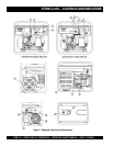
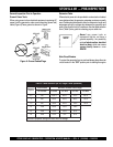
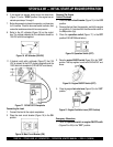
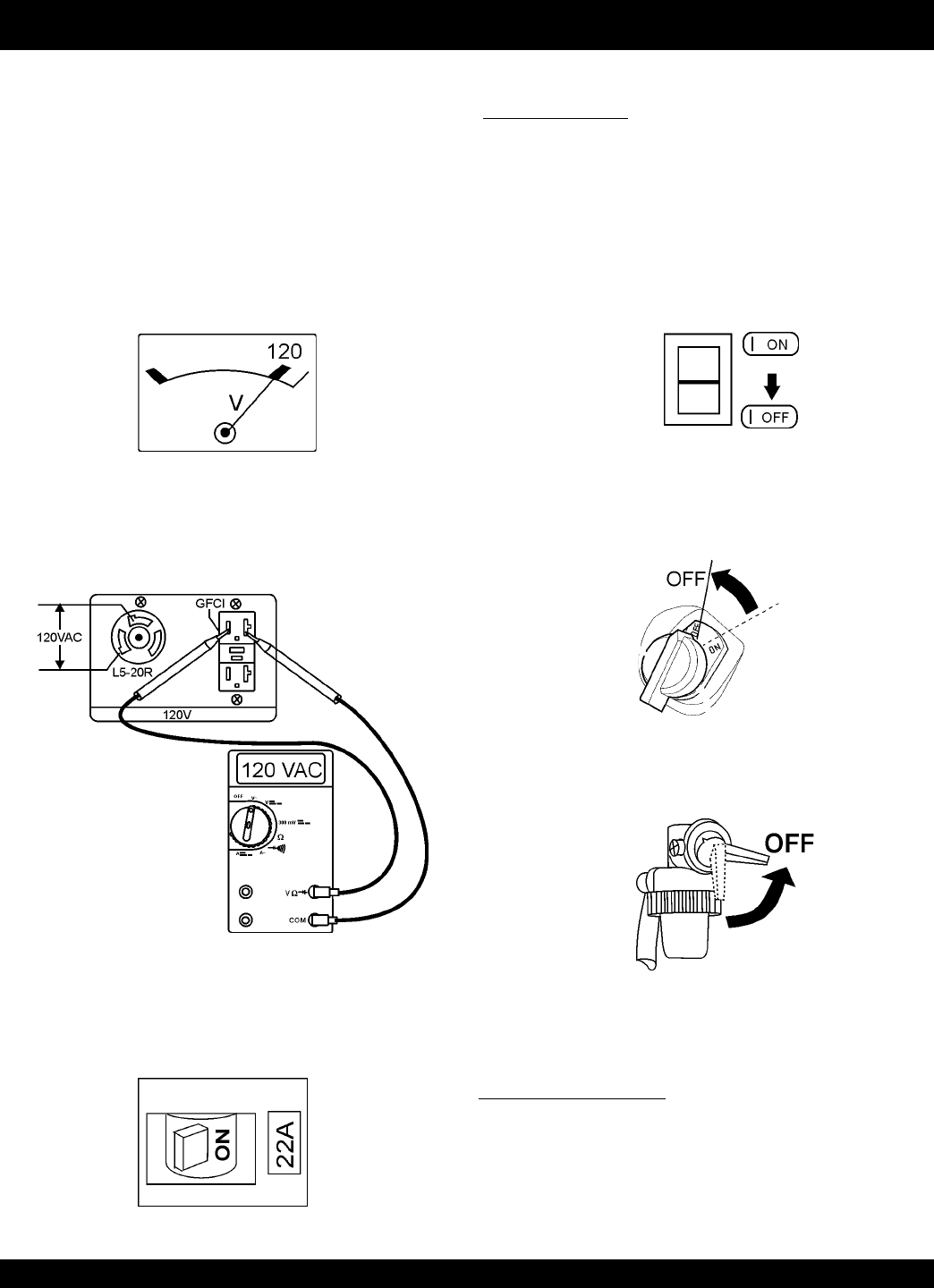
8. Refer to the AC voltmeter (Figure 16) on the control
box. The voltage indicated on the voltmeter should be
120 VAC with no load applied.
Figure 16. AC Voltmeter (120 VAC)
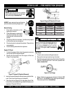
11. If desired, verify with a voltmeter (Figure17) that 120
VAC is present at the GFCI duplex receptacle and the
120V twist-lock receptacle (S/N 5497957 and above).
STOW G-2.9R — INITIAL START-UP ENGINE/OPERATION
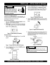
Connecting the Load
1. Connect the load to the output receptacles.
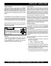
2. Place the main circuit breaker (Figure 18) in the ON
position.
Figure 17. 120 VAC GFCI Receptacle
Stopping The Engine
Normal Shutdown
1. Place the
main circuit breaker
(Figure 10) in the OFF
position.
2. Remove the load from the generator, and let the engine
run at idle for 3-5 minutes with the idle control switch in
the ON position (Up)
3. Place the
operation switch
(Figure 17) in the OFF
position S/N 5497956 and below).
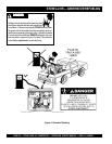
6. Place the engine
fuel valve lever
(Figure 21) to the "OFF"
position.
”
Emergency Showdown
1. Place the
operation switch or engine ON/OFF swith
(Figures19 or 20) in the "OFF" position.
Figure 19. Operation Switch (OFF)
Figure 21. Engine Fuel Valve Lever (OFF Position)
Figure 20. Engine ON/OFF Switch (OFF)
5. Place the
engine ON/OFF switch
(Figure 20) in the "
OFF
"
position. This step applies to units with S/N 5497957 and
above.
Figure 18. Main Circuit Breaker (ON)